© Copyright 2020 Zoeller Company All rights reserved.
CONTROL/MECHANICAL SWITCH WIRING
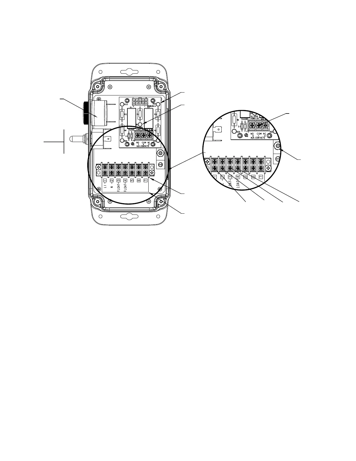
Connectthetwoconductorsfromthehighwateroatswitchtoinputterminalsasdescribedaboveforthealarmunit(seeFigureB).Thealarmswitch
operates on low voltage to reduce shock hazards. The auxiliary contacts may be used to control another alarm circuit away from the location of the
APak
™
Outdoor High Water Alarm system.
OPERATION AND TESTING
Checkandtestyourinstallationbyliftingtheoatmanually.ThealarmunitwillindicateanalarmconditionbybuzzerchirpingandlightingtheredLEDs.
Thealarmmaybesilencedfor24hoursbybrieypressingtheSilencetoggleswitch.Oncesilenced,theRedLEDswillremainonbutthebuzzerwillnot
sound. Once the high-water condition is remedied, the alarm should be reset by holding the Silence toggle switch for 2 seconds. Hold the Silence toggle
switch up to Test once per week to verify proper operation.
Figure B
TERMINAL BLOCK
TERMINAL BLOCK LABEL
GROUND LUG
(4) ALARM LED
POWER ON LED
ALARM BUZZER
TEST
TOGGLE
SWITCH
SILENCE/
RESET
LINE
NEUTRAL
FLOAT
FLOAT


 To Next Page