SPECIFICATIONS
UNIVERSAL RELAY
ZEN17
www.getzooz.com
ask@getzooz.com
USER MANUAL
FEATURES
Ÿ Powerful dry contact NO/NC relays to control loads up to 20 A for NO
Ÿ Perfect for DC motors, pumps, commercial gates, or HVAC equipment
Ÿ Control up to 2 connected loads independently or together
Ÿ Z-Wave or optional wall switch control (toggle or momentary type)
Ÿ Monitor inputs independently from output control
Ÿ Built-in timers for each relay to simplify automation
Ÿ Built-in Z-Wave Plus signal repeater to extend network range
Ÿ Powered by 12-24 V DC/AC or USB C port for easy set-up
Ÿ Wall mounting and minimal design for clean installation
Ÿ NEW 700 Z-Wave chip, S2 security, and SmartStart
Ÿ Model Number: ZEN17
Ÿ Z-Wave Signal Frequency: 908.42 MHz
Ÿ Power: 12-24 V DC/AC or USB C (DON’T use laptop / tablet chargers)
Ÿ Maximum Load: NO relays: 20 A, NC relays: 10 A
Ÿ Inputs: dry contact or 12-24 V AC/DC (use 1 input type at a time!)
Ÿ Range: Up to 200 feet line of sight
Ÿ Operating Temperature: 32-104° F (0-40° C)
Ÿ Installation and Use: Indoor only
CAUTION
This is an electrical device - please use caution when installing and
operating the MultiRelay. Remote control of appliances may result in
unintentional or automated activation of power.
WIRING: READ IT!
This device is intended for installation in accordance with
the National Electric Code and local regulations. It is
recommended that a licensed electrician perform this
installation. USE A SINGLE POWER SOURCE AT ALL TIMES.
BEFORE YOU INSTALL
1. CHECK THE LOAD: make sure that the connected appliance does not
exceed 20 A for normally open relays or 10 A for normally closed relays.
2. POWER OFF: turn the circuit power off in the breaker panel before
you start. If handling wiring from a box with multiple circuits, turn
power off at all of the circuits.
3. REMOVE THE WALL SWITCH: if the load is currently controlled by a
wall switch, carefully remove it from the box and disconnect the wires
from the switch.
4. CONNECT THE UNIVERSAL RELAY: follow the instructions in the
appropriate diagram for your set-up. If you can’t find your scenario in
the diagrams below, please request custom instructions from our
support team, we’re happy to help: ask@getzooz.com
WIRING TIPS
µ
Before you disconnect any wires, document your set-up and send us
images of your existing installation so we can help if needed.
@
Always use the correct screwdriver size for the terminal screws on your
Universal Relay and wall switches (if connecting them). Use appropriate
electrical tools when cutting, prepping, and stripping electrical wires. If
you don’t have the necessary tools to perform the installation or are not
sure which tools to use or how, please hire an electrician to complete
the installation for you.
~
Follow the National Electrical Code and your local safety regulations
when performing the installation, including (but not limited to), choo-
sing the correct gauge of jumper wires. The recommended gauge for 15
Amp circuits is 14 AWG and 12 AWG for 20 Amp circuits.
PAGE 2PAGE 1
TAKE PICTURES
GATHER YOUR TOOLS
SAFETY FIRST
HOW TO SECURE WIRES IN TERMINALS: first, unscrew the appropriate
terminal’s screw just far enough so there is a clear opening in the termi-
nal for the wire to go in. Make sure the wire is stripped at the right length
and perfectly straight before you insert it into the terminal. Once you
put the wire in the terminal, carefully screw the terminal screw back in
to hold down the wire. Check the connection by gently pulling on the
connected wire to make sure it’s fixed securely.
5. POWER THE UNIVERSAL RELAY: connect the USB C power source to
the MultiRelay or use the “+” “-” terminals on the device to bring low
voltage power to it. Never use both at the same time. In both cases
you’ll need a standard 1 A power adapter to plug into a standard 120
VAC receptacle. Do NOT use with laptop or tablet chargers, they
require a large battery on load to activate.
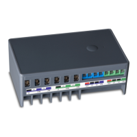
WHAT’S WHAT
INPUT TERMINALS RELAY TERMINALS
S1 C: wall switch to control R1 or dry contact sensor to monitor leaks
(max 40k Ohm when on), open/close status, or motion.
C : 12-24 V DC / AC input to control R1. NEVER use C VC and S1 C VC
together! Only one type of input can be used at any given time.
S2 C: wall switch to control R2 or dry contact sensor to monitor leaks,
open/close status, or motion.
C : 12-24 V DC / AC input to control R2. NEVER use C VC and S1 C VC
together! Only one type of input can be used at any given time.
NC C R1: normally closed relay controlling any load up to 10 A.
NO C R1: normally open relay controlling any load up to 20 A.
NC C R2: normally closed relay controlling any load up to 10 A.
NO C R2: normally open relay controlling any load up to 20 A.
WIRING EXAMPLE
DC
MOTOR
12-24 V DC
POWER SUPPLY
+
-
0
WALL SWITCH
ZEN17 WIRING DIAGRAM
FOR DC MOTORS
(UP/DOWN, OPEN/CLOSE)
POOL PUMP: 120 / 220 V to R1 C, neutral to neutral, pump (load) to
R1 NO.
WHOLE-HOUSE FAN: 120 V to R1 C, neutral to neutral, fan low speed
to R1 NO; fan high speed to R2 NO.
LANDSCAPE LOW-VOLTAGE LIGHTING: one leg from power supply to
R1 C, the other leg from power supply to lights; R1 NO to the other
input on the lights.
SPRINKLERS: one leg from power supply to R1 C, the other leg from
power supply to sprinkler valve; R1 NO to the other input on the
valve. Automate up to 2 zones with R1 and R2.
GARAGE DOOR OPENER: 2 bell wires from the opener to R1 C and R1
NO; 2 wires from the wall switch to S1 and C.
LOW-VOLTAGE ALARM INPUT: 12-24 V wires to C and VC terminals.
LEAK ALARM INPUT: water sensor wires to S1 and C (max 40k Ohm)
DOOR SENSOR INPUT: open/close sensor wires to S1 and C.
WIRING GUIDE
1 POWER SUPPLY AT A TIME
Never use USB C and 12-24 V power supply together. Double power
source will damage the device.
1 INPUT TYPE AT A TIME
Never connect inputs to S1 C and VC C for the same relay. Each relay
can only have a single input type.
NO VOLTAGE ON “S” TERMINALS
The only input terminals that accept voltage are the C VC terminals.