TEST THE SWITCH
The LED indicator should light up as soon as you turn the power back on if
the switch (light) is OFF. Tap the upper paddle of the dimmer for ON and
lower paddle for OFF. If the test fails, please check that:
Ÿ power is fully restored to the circuit
Ÿ wiring matches the instructions exactly
Ÿ the type of load is approved and within the specs of this switch
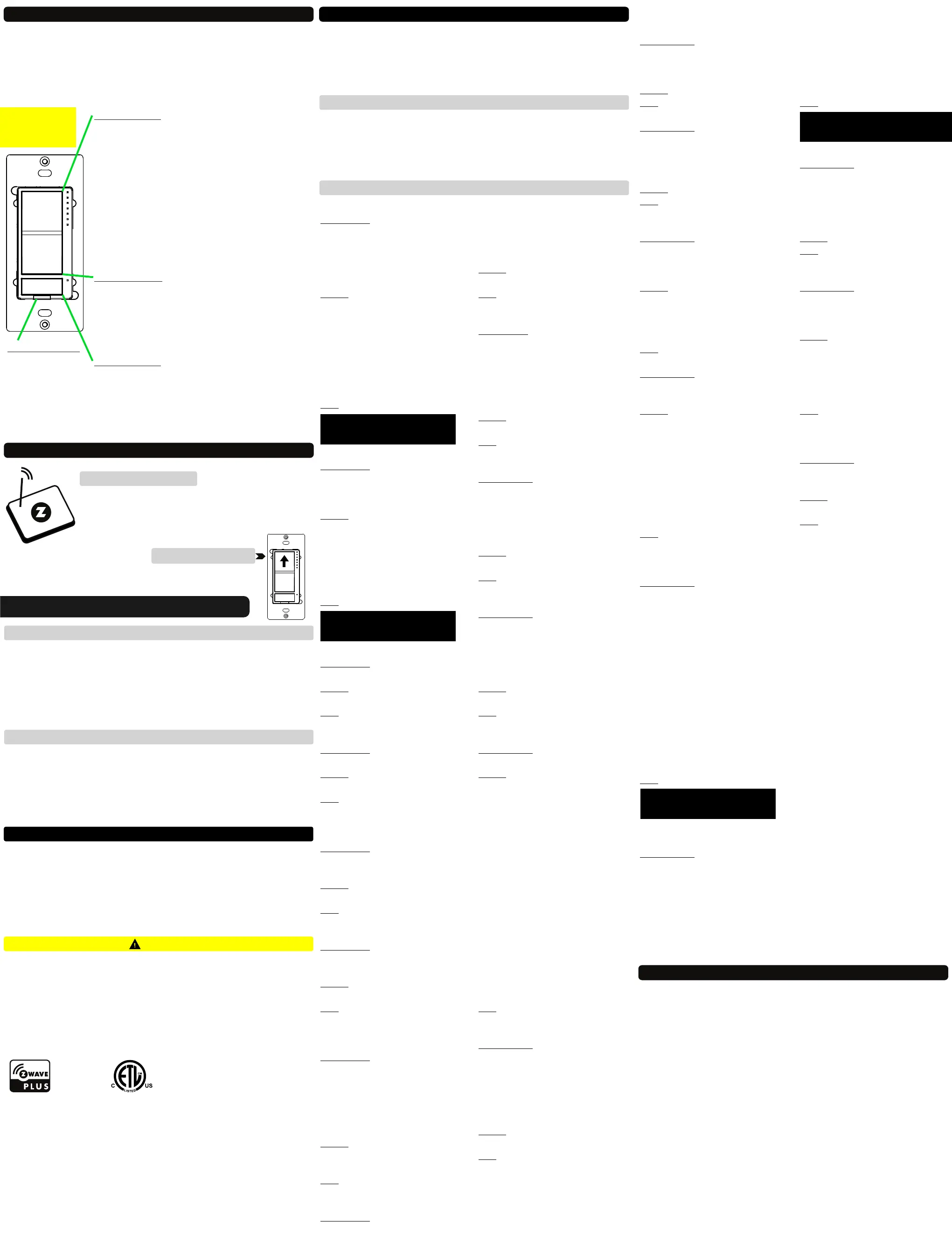
UPPER PADDLE
1 TAP: turn the light on to the last brightness level
(or custom brightness: see Parameter 23). It takes
around a second for the dimmer to reach full
brightness. See Parameters 13 and 22 to change the
ramp rate.
2 x TAP: go to full (or custom) brightness (see
Parameters 17 and 18 to customize).
3 x TAP: inclusion mode active for 30 seconds.
6 x TAP: change LED indicator mode for dimmer
(see Parameter 1 for details).
PRESS AND HOLD: add brightness.
LOWER PADDLE
1 TAP: turn the light off.
3 x TAP: exclusion mode active for 30 seconds.
4 x TAP’N’HOLD for 10 seconds: disable manual
control for the dimmer paddles.
PRESS AND HOLD: reduce brightness.
RELAY BUTTON
1 TAP: turn the load on or off (change state).
6 x TAP: change LED indicator mode for relay (see
Parameter 2 for details).
4 x TAP’N’HOLD for 10 seconds: disable manual
control for the relay button.
MANUAL
CONTROL
AIR-GAP SWITCH
Pull it out when
changing bulbs to
cut off power to
the switch for
your safety and
shock prevention.
Z-WAVE CONTROL
1. ADD DEVICE to your hub
Initiate inclusion (pairing) in the app (or web interface).
Not sure how? Get step-by-step instructions for adding
the switch to SmartThings, Vera, Wink and other hubs
here: www.support.getzooz.com
NEED SOME HELP? ask@getzooz.com
TAP 3 TIMES QUICKLY
2. Finalize inclusion at the switch.
The LED indicators will blink to signal communication
and remain on for 2 seconds to confirm inclusion.
1. Bring your Z-Wave gateway (hub) close to the switch if possible
2. Put the Z-Wave hub into exclusion mode (not sure how to do that?
ask@getzooz.com)
3. Tap the lower paddle on the dimmer 3 times quickly
4. Your hub will confirm exclusion and the device will disappear from your
controller's device list
EXCLUSION (REMOVING / UNPAIRING DEVICE)
FACTORY RESET
TROUBLESHOOTING
The switch won’t add to your system? Try this:
1. Initiate EXCLUSION and tap the lower paddle 3 times quickly.
2. Tap the upper paddle 4-5 times quickly when adding it.
3. Bring the gateway controller (hub) closer to the switch, it may be out
of range.
4. Get troubleshooting tips for your hub at www.support.getzooz.com
If your primary controller is missing or inoperable, you may need to reset
the device to factory settings. To complete the reset process manually,
press and hold the lower paddle on the dimmer for at least 15 seconds
until the LED indicators start flashing, then release. Then immediately
press and hold the upper paddle on the dimmer for at least 15 seconds.
The LED indicators will flash again to confirm successful reset.
NOTE: All previously recorded activity and custom settings will be erased from the device’s memory.
Ÿ This product should be installed indoors upon completion of any building renovations.
Ÿ Prior to installation, the device should be stored in a dry, dust-and-mold-proof place.
Ÿ Do not install the switch in a place with direct sun exposure, high temperature, or
humidity.
Ÿ Keep away from chemicals, water, and dust.
Ÿ Ensure the device is never close to any heat source or open flame to prevent fire.
Ÿ Ensure the device is connected to an electric power source that does not exceed the
maximum load power.
Ÿ No part of the device may be replaced or repaired by the user.
WARNING
This product can be included and operated in any Z-Wave network with
other Z-Wave certified devices from other manufacturers and/or other
applications. All non-battery operated nodes within the network will act as
repeaters regardless of vendor to increase reliability of the network.
This product features the latest Security 2 (S2) framework to remove smart
home network hacking risks. This device is equipped with a unique
authentication code for trusted wireless communication.
This is an ETL certified device. ETL, just like UL, is a Nationally
Recognized Testing Laboratory. The ETL mark is proof of product
compliance with North American safety standards.
S2
PAGE 4 PAGE 5 PAGE 6
ADVANCED SETTINGS
Please refer to your controller's user guide for advanced programming
instructions as they are a little different for every soware.
Not sure where to start? Go to www.support.getzooz.com for detailed
instructions on how to change the settings on SmartThings, Vera, and
more. Or just email us: ask@getzooz.com
ASSOCIATION
The Double Switch supports Group 1 with up to 1 devices for lifeline com-
munication. The dimmer supports Group 2 with up to 5 devices and will
send BASIC_SET report to other devices in Group 2 to communicate status
changes. and will send The relay supports Group 3 with up to 5 devices
BASIC_SET report to other devices in Group 3 if its status changes.
CUSTOMIZE YOUR SWITCH
LED Indicator Mode for Dimmer
Parameter 1: Choose if you want the
LED indicator to turn on when the
switch (light) is on or off, or if you
want it to remain on or off at all
times. This setting is for the top status
indicator only.
Values: 0 – LED indicator is on when
switch is off, LED indicator is off when
switch is on (default); 1 – LED
indicator is on when switch is on, LED
indicator is off when switch is off; 2 –
LED indicator is always off and LED’s
don’t indicate brightness level during
dimming; 3 – LED indicator is always
on.
Size: 1 byte dec.
LED Indicator Control for Relay
Parameter 2: Choose if you want the
LED indicator to turn on when the
relay is on or off, or if you want it to
remain on or off at all times
Values: 0 – LED indicator is on when
relay is off, LED indicator is off when
relay is on (default); 1 – LED indicator
is on when relay is on, LED indicator
is off when relay is off; 2 – LED
indicator is always off; 3 – LED
indicator is always on
Size: 1 byte dec.
LED Indicator Color for Dimmer
Parameter 3: Choose the color of the
LED indicators for the dimmer.
Values: 0 – white (default); 1 – blue; 2
– green; 3 – red.
Size: 1 byte dec.
LED Indicator Color for Relay
Parameter 4: Choose the color of the
LED indicator for the relay.
Values: 0 – white (default); 1 – blue; 2
– green; 3 – red.
Size: 1 byte dec.
LED Indicator Brightness for
Dimmer
Parameter 5: Choose the LED
indicators’ brightness level for the
dimmer.
Values: 0 – bright (100%); 1 – medium
(60%); 2 – low (30%). Default: 1.
Size: 1 byte dec.
LED Indicator Brightness for Relay
Parameter 6: Choose the LED
indicators’ brightness level for the
relay.
Values: 0 – bright (100%); 1 – medium
(60%); 2 – low (30%). Default: 1.
Size: 1 byte dec.
LED Indicator Mode for Scene
Control
Parameter 7: Choose if you want the
LED indicators next to the dimmer to
light up when a scene is selected.
You’ll see 1 to 5 LEDs light up for 1 – 5
tap triggers and 6 LEDs light up for
the press-and-hold trigger of any
paddle / button used.
Values: 0 – LEDs enabled to indicate
scene triggers; 1 – LEDs disabled to
indicate scene triggers (default).
Size: 1 byte dec.
Auto Turn-Off Timer for Dimmer
Parameter 8: Use this parameter to
set the time aer which you want the
dimmer to automatically turn off
once it has been turned on. The
number entered as value
corresponds to the number of
minutes.
Values: 0 – timer disabled (default); 1
– 65535 (minutes).
Size: 4 byte dec.
Auto Turn-On Timer for Dimmer
Parameter 9: Use this parameter to
set the time aer which you want the
dimmer to automatically turn on
once it has been turned off. The
number entered as value
corresponds to the number of
minutes.
Values: 0 – timer disabled (default); 1
– 65535 (minutes).
Size: 4 byte dec.
Auto Turn-Off Timer for Relay
Parameter 10: Use this parameter to
set the time aer which you want the
relay to automatically turn off once it
has been turned on. The number
entered as value corresponds to the
number of minutes.
Values: 0 – timer disabled (default); 1
– 65535 (minutes).
Size: 4 byte dec.
Auto Turn-On Timer for Relay
Parameter 11: Use this parameter to
set the time aer which you want the
relay to automatically turn on once it
has been turned off. The number
entered as value corresponds to the
number of minutes.
Values: 0 – timer disabled (default); 1
– 65535 (minutes).
Size: 4 byte dec.
On Off Status Aer Power Failure
Parameter 12: Set the on/off status of
the device aer power failure.
Values: 0 – dimmer and relay forced
to off (regardless of state prior to
power outage);
1 – dimmer forced to off, relay forced
to on;
2 – dimmer forced to on, relay forced
to off;
3 – remembers and restores on/off
status for dimmer and relay aer
power failure (default);
4 – remembers and restores on/off
status for dimmer, relay forced to on;
5 – remembers and restores on/off
status for dimmer, relay forced to off;
6 – dimmer forced to on, remembers
and restores on/off status for relay;
7 – dimmer forced to off, remembers
and restores on/off status for relay;
8 – dimmer and relay forced to on.
Size: 1 byte dec.
Ramp Rate Control for Dimmer
Parameter 13: Adjust the ramp rate
for the dimmer (fade-in / fade-out
effect for on/off operation). Values
correspond to the number of seconds
it takes for the dimmer to reach full
brightness or turn off when operated
manually.
Values: 0 – instant on/off; 1 – 99
(seconds). Default: 1.
Size: 1 byte dec.
Minimum and Maximum
Brightness
Parameter 14: Set the minimum
brightness level (in %) for the
dimmer. You won’t be able to dim
the light below the set value.
Values: 1 – 99 (%). Default: 1.
Size: 1 byte dec.
Parameter 15: Set the maximum
brightness level (in %) for the
dimmer. You won’t be able to add
brightness to the light beyond the
set value.
Values: 1 – 99 (%). Default: 99.
Size: 1 byte dec.
Double Tap Function for Dimmer
Parameter 17: Choose if you want the
dimmer to turn on to full brightness
or custom brightness level aer you
double-tap the upper paddle.
Values: 0 – the light will turn on to full
brightness with double tap (default).
1 – the light will turn on to the
maximum brightness level set in
Parameter 15 with double tap.
Size: 1 byte dec.
Parameter 18: Enable or disable the
double-tap function and assign
brightness level to single tap.
Values: 0 – double tap to full /
maximum brightness level enabled
(default).
1 – double tap to full / maximum
brightness level disabled, single tap
turns light on to last brightness level
(or custom value set in Parameter
23). 2 – double tap to full / maximum
brightness level disabled, single tap
turns light on to full brightness level.
Size: 1 byte dec.
Enable/Disable Load Control for
Dimmer (Smart Bulb Setting)
Parameter 19: Enable or disable
direct manual and Z-Wave control of
the connected light. Works great for
smart bulb control. If disabled, the
dimmer will no longer control the
connected bulb directly but will still
send on/off and brightness reports to
the hub so you can use them to
create automations for your smart
bulbs or other switches. Scenes and
other functionality will still be
available through paddles.
Values: 0 – manual control disabled.
1 – manual control enabled (default).
2 manual and Z-Wave control –
disabled.
Size: 1 byte dec.
Enable/Disable Load Control for
Relay (Remote Control Setting)
Parameter 20: Enable or disable
direct manual and Z-Wave control of
the connected load. Works great for
smart bulbs or any type of remote /
scene control. If disabled, the relay
will no longer control the connected
load directly but will still send on/off
reports to the hub so you can use
them to create automations for your
smart bulbs or other devices. Scenes
and other functionality will still be
available through the button.
Values: 0 – manual control disabled.
1 – manual control enabled (default).
2 manual and Z-Wave control –
disabled.
Size: 1 byte dec.
Manual Dimming Speed
Parameter 21: Choose how many
seconds it takes for the dimmer to go
from 0% to 100% brightness when
pressing and holding the paddle.
Increase the value to decrease the
dimming speed.
Values: 1 – 99 (seconds). Default: 4.
Size: 1 byte dec.
Z-Wave Ramp Rate for Dimmer
Parameter 22: Choose if you would
like to match the Z-Wave on/off ramp
rate with the manual ramp rate or set
it separately in your hub.
Values: 0 – Z-Wave on/off ramp rate
matches the manual ramp rate set in
Parameter 13. 1 – Z-Wave on/off
ramp rate is set separately through
its command class in the hub.
Default: 0.
Size: 1 byte dec.
Default Brightness Level On for
Dimmer
Parameter 23: Set custom brightness
level (in %) for the dimmer to come
on to at single tap.
Values: 0 – last brightness level
(default); 1 – 99 (%).
Size: 1 byte dec.
SCENE CONTROL
You can trigger up to 18 scenes or
control up to 18 independent Z-Wave
devices in your network using the
Double Switch.
You can assign scenes to 1-tap, 2-tap,
3-tap, 4-tap, 5-tap, or press-and-hold
for any of the paddles and the relay
button. Your hub needs to support
central scene implementation for
this feature to be available.
Find out how to make scene
control work on your hub at
www.support.getzooz.com
This device requires the following
command classes to be supported
and recognized by your Z-Wave
controller:
COMMAND_CLASS_ZWAVEPLUS_INFO
COMMAND_CLASS_SWITCH_MULTILEVEL
COMMAND_CLASS_SWITCH_BINARY
COMMAND_CLASS_ASSOCIATION
COMMAND_CLASS_MULTI_CHANNEL_ASSOCIATION
COMMAND_CLASS_ASSOCIATION_GRP_INFO
COMMAND_CLASS_TRANSPORT_SERVICE
COMMAND_CLASS_VERSION
COMMAND_CLASS_MANUFACTURER_SPECIFIC
COMMAND_CLASS_DEVICE_RESET_LOCALLY
COMMAND_CLASS_POWERLEVEL
COMMAND_CLASS_CONFIGURATION
COMMAND_CLASS_CENTRAL_SCENE
COMMAND_CLASS_MULTI_CHANNEL
COMMAND_CLASS_SECURITY_2
COMMAND_CLASS_SUPERVISION
COMMAND_CLASS_FIRMWARE_UPDATE_MD
WARRANTY
This product is covered under a 12-month limited warranty. To read the full warranty
policy or file a warranty claim, please go to www.getzooz.com/warranty
IN NO EVENT SHALL ZOOZ OR ITS SUBSIDIARIES AND AFFILIATES BE LIABLE FOR ANY INDIRECT, INCIDENTAL, PUNITIVE, SPECIAL, OR
CONSEQUENTIAL DAMAGES, OR DAMAGES FOR LOSS OF PROFITS, REVENUE, OR USE INCURRED BY CUSTOMER OR ANY THIRD PARTY,
WHE-THER IN AN ACTION IN CONTRACT, OR OTHERWISE EVEN IF ADVISED OF THE POSSIBILITY OF SUCH DA-MAGES. ZOOZ'S LIABILITY
AND CUSTOMER'S EXCLUSIVE REMEDY FOR ANY CAUSE OF ACTION ARISING IN CON-NECTION WITH THIS AGREEMENT OR THE SALE
OR USE OF THE PRODUCTS, WHETHER BASED ON NEGLIGENCE, STRICT LIABILITY, BREACH OF WARRANTY, BREACH OF AGREEMENT,
OR EQUITABLE PRINCIPLES, IS EXPRESSLY LIMITED TO, AT ZOOZ'S OPTION, REPLACEMENT OF, OR REPAYMENT OF THE PURCHASE
PRICE FOR THAT POR-TION OF PRODUCTS WITH RESPECT TO WHICH DA-MAGES ARE CLAIMED. ALL CLAIMS OF ANY KIND ARISING IN
CONNECTION WITH THIS AGREEMENT OR THE SALE OR USE OF PRODUCTS SHALL BE DEEMED WAIVED UNLESS MADE IN WRITING
WITHIN THIRTY (30) DAYS FROM ZOOZ'S DELIVERY, OR THE DATE FIXED FOR DELI-VERY IN THE EVENT OF NONDELIVERY.
FCC NOTE
THE MANUFACTURER IS NOT RESPONSIBLE FOR ANY RADIO OR TV INTERFERENCE CAUSED BY UNAUTHORIZED MODIFICATIONS TO
THIS EQUIPMENT. SUCH MODIFICATIONS COULD VOID THE USER’S AUTHORITY TO OPERATE THE EQUIPMENT. STORE INDOORS WHEN
NOT IN USE. SUITABLE FOR DRY LOCATIONS ONLY. DO NOT IMMERSE IN WATER. NOT FOR USE WHERE DIRECTLY EXPOSED TO WATER.
This device complies with Part 15 of the FCC Rules.
Operation is subject to the following conditions:
1. This device may not cause harmful interference,
2. This device must accept any interference received, including interference that may cause undesired operation.
This equipment has been tested and found to comply with the limits for a Class B digital device, pursuant to part 15 of the FCC Rules.
These limits are designed to provide reasonable protection against harmful interference in a residential installation.
This equipment generates, uses and can radiate radio frequency energy and, if not installed and used according to instructions, may
cause harmful interference to radio communications.
However, there is no guarantee that interference will not occur in any given installation.
If this equipment causes harmful interference to radio or television reception, the user may try to correct the interference by taking one
or more of the following measures:
- Reorient or relocate receiving antenna
- Increase the separation between equipment and receiver
- Connect equipment into a separate outlet or circuit from receiver
- Consult the dealer or an experienced radio/TV technician for additional assistance
All brand names displayed are trademarks of their respective holders.
© Zooz 2019
4 TAP’N’HOLD LOWER PADDLE
to change the mode.
OR:
4 TAP’N’HOLD THE BUTTON
to change the mode.
OR:
6 x TAP UPPER PADDLE
to change the LED mode.
OR:
6 x TAP RELAY BUTTON
to change the LED mode.
OR:
 Loading...