Chapter2SystemStructureandComponents
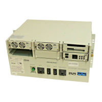
Figure2-2ChassisStructure(RearView)
1.Rearpanel
2.ACinputcablinghole
3.Batteryinputconnection
terminals(BATT1,BATT2,
BATT3)(-48V)
4.MainDCoutputconnection
terminals(MAINOUTPUT)
(-48V)
5.-48Vbusbar(-48V)
6.Workinggroundbusbar
(+/RTN)
7.ACinputconnection
terminals(L,N,L,N,PE)
Foradescriptionofthecomponents,refertoT able2-2.
Table2-2ChassisComponents(RearView)
S.N.ComponentDescription
1RearpanelRemovetherearpanelbeforeconnectingthecables.
2ACinputcablingholeCablingholefortheACinputcables(L,N,L,N,PE)
3Batteryinputconnection
terminals(BATT1,BATT2,
BATT3)(-48V)
Connectbatterypackstothesystem.
4MainDCoutputconnection
terminals(MAINOUTPUT)
(-48V)
Connect-48VterminalsofthemainDCload.
2-3
SJ-20120703093141-002|2013-01-08(R1.2)ZTEProprietaryandCondential
 Loading...