Do you have a question about the 2easy DMR21/D32/F1 and is the answer not in the manual?
Provides an overview of the modular design and flexibility of the intercom system.
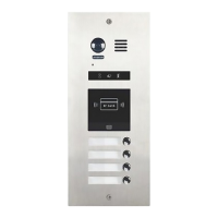
Identifies and describes the physical components and their basic functionalities.
Details the various terminal connections and their purposes for system integration.
Explains how to access and replace the nameplate for user identification.
Describes the procedures for physically installing the door station units.
Illustrates the wiring diagrams for connecting multiple door stations and power.
Explains how to configure system settings using DIP switches on the door station.
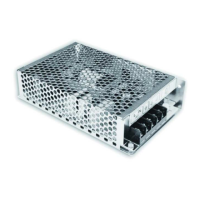
Details how to connect electronic locks, both with internal and external power.
Specific guidance for configuring door lock operation using an external power supply.
Lists the technical specifications of the door station, including power and dimensions.
Details the Camera Module's parts, functions, and various settings like unlocking modes and volume.
Covers the Keypad Module's components, operations with TFT, and extensive parameter settings.
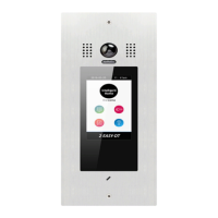
Explains the TFT Display Module's features, functions, and user interface for calling and conversation.
Outlines the Card Reader Module's features, capacity, master card operations, and user card management.
Describes the Call Button Module's parts, functions, and how call codes are assigned to buttons.
Shows terminal descriptions and connections for the video entry module.
Illustrates terminal descriptions and connections for the card reader module.
Displays terminal descriptions and connections for the call button module.
Shows terminal descriptions and connections for keypad and TFT modules.
Provides a connection diagram for the DMR21/D16 system configuration.
Illustrates the connection diagram for the DMR21/ID/S4 system.
Shows the connection diagram for the DMR21/T4/D8 system configuration.
Presents the connection diagram for the DMR21/ID/KP system.
Displays the connection diagram for the DMR21/S8+F3 system.
Shows the connection diagram for the DMR21/ID/KP system configuration.
Guides on setting up the door station namelist, work modes, and calling methods.
Details the process for updating the door station's firmware using an SD card.
Explains how to update the system's ringtones by copying a file to an SD card.
Provides instructions for updating the namelist on the door station via an SD card.
| Brand | 2easy |
|---|---|
| Model | DMR21/D32/F1 |
| Category | Intercom System |
| Language | English |