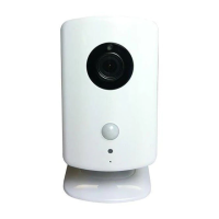
RESETTING THE SENSOR
Before programming the image sensor into a new network,
you must reset it as follows:
1. Insert a paperclip into the hole on the front of the
sensor to access the Reset buon.
2. Press and hold the Reset buon for three (3) seconds.
This power cycles the sensor.
3. Hold down the Reset buon for 10 seconds. When the
LED begins flashing, the sensor is reset and is removed
from the exisng network.
NOTE: If the image sensor is not communicang with its
network, you can use the Reset buon to clear the sensor
from that network. If the sensor is sll communicang with
its network, clear sensor by deleng it from the control
panel.
SENSOR RESET HOLE
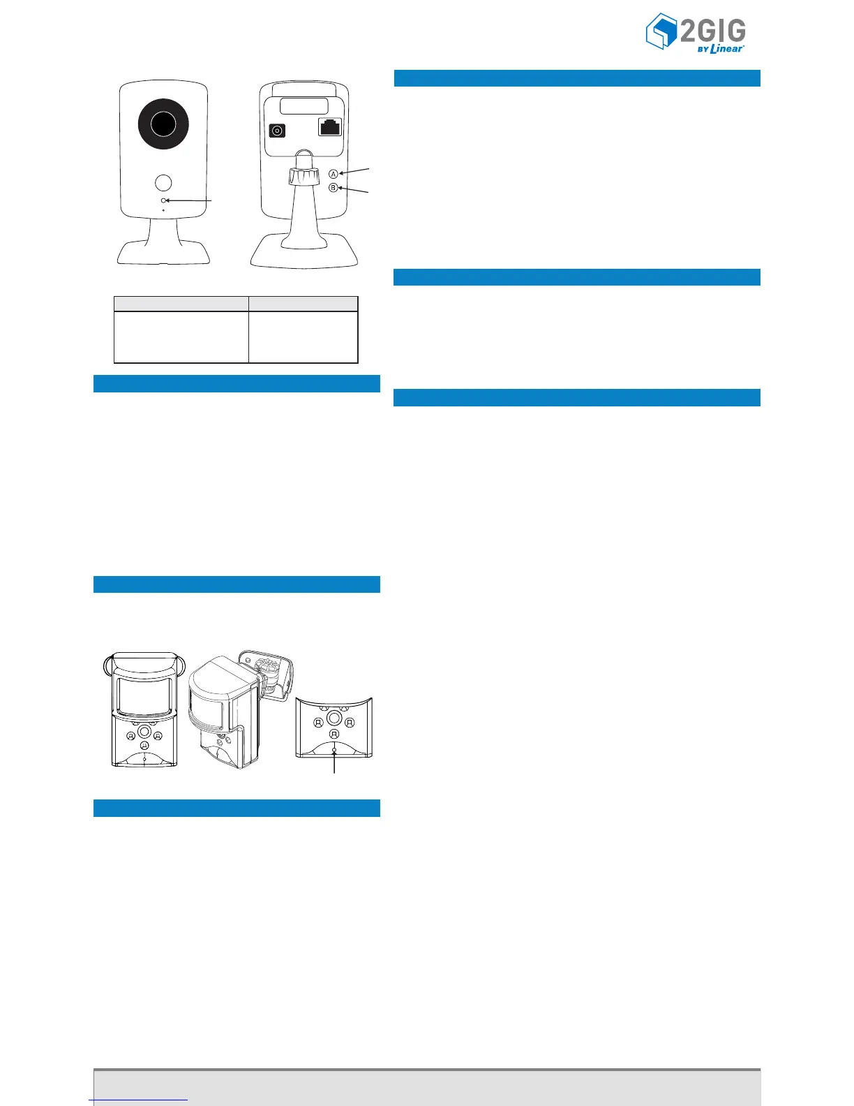
WIFI TO THE ON-SITE ROUTER (WPS)
1. If the on-site router supports WiFi Protected Setup (WPS), press
the WPS buon (A) unl the routher enters WPS mode (the
indicators will differ slightly from router to router). This gives the
routher the ability to “listen” for a new WPS device.
2. Press the WPS buon (A) on the camera. This acon causes the
camera to announce itself to the router as a WPS device. While the
camera is in WPS mode, the LED on the camera blinks YELLOW.
3. Do not press any buons on the camera unl its LED illuminates
GREEN, which indicates the camera has successfully connected to the
network.
4. From the Alarm.com website add and configure the camera.
WIFI TO THE ON-SITE ROUTER
1. Connect the camera directly to the router using an ethernet cable.
2. From the Alarm.com website add and configure the camera to
connect using WiFi.
3. Disconnect the power cable from the camera.
4. Disconnect the Ethernet cable from the camera. A WiFi connecon
will be established.
ETHERNET TO THE ROUTER
1. Connect the camera directly to the router using an Ethernet cable.
2. From the Alarm.com website add and configure the camera.
NOTE: Access points and cellular “hot spots” will not work with the
HD100 Camera. You must have a router installed in the home.
LED
WPS
RESET
LED States
State LED Pattern
Normal Operation Solid Green
Connectivity Problems Blinking Red
WPS Transaction in Progress Blinking Yellow
Booting Solid Yellow
77-000010-001 Rev D
For technical support in the USA and Canada: 855-2GIG-TECH (855-244-4832) or visit the
2GIG dealer site at dealer.2gig.com, or email us at 2gigtechsupport@linearcorp.com.
For technical support outside of the USA and Canada, contact your regional distributor.
Copyright © 2014 Linear LLC.
1. CREATE AN ALARM.COM CUSTOMER ACCOUNT. When creang an
account on the Alarm .com dealer site, enter the serial number for the
2GIG CDMA Cell Radio Module (2GIG-GC CDMA).
2. VERIFY THE CELL RADIO AND TRANSCEIVER INSTALLATION. Ensure that
the 2GIG-GC CDMA and 2GIG-XCVR2 radio are properly installed and
connected inside the control panel. The firmware version must be v1.10
(or higher).
3. REGISTER MODULE AND TEST COMMUNICATIONS. Power up the panel
and iniate a cell phone test to ensure the communicaon module is
properly installed and communicang with Alarm.com.
4. PROGRAM THE SENSOR INTO THE CONTROL PANEL. Enter the control
panel’s System Configuraon module (see page 1).
Select: RF Sensor # (01 to 48)to select the desired zone opon. Then
tap
Select: RF Sensor # Typeto select (04) Interior Follower, (10) Interior
with Delay, or (3) No Response Type. Then tap
Select: RF Sensor # Equipment Typeto select (1) Moon. Then tap
Select: RF Sensor Equipment Codeto select (9999) Alarm.com Image
Sensor. Then tap
Enter: RF Sensor # Serial Number (Read Only) Use the MAC address
(must be learned into the panel).
Select: RF Sensor # Equipment Age (0 to 1)to select (0) New or (1)
Exisng. Then tap
Select: RF Sensor # Loop Number (0 to 3)to select (1) 1. Then tap
Select: RF Sensor # Dialer Delay (0 to 1) to select (0) Disabled. Then
tap
Construct: RF Sensor # Voice Descriptor
Tap Insert. Then tapto scroll through the available words or
enter the 3-digit code associated with the desired word. See
Voice Descriptors on page 4. Then tap
Select: RF Sensor # Reports (0 to 1)to select (1) Enabled. Then tap
Select: RF Sensor # Supervised (0 to 1)to select (1) Enabled. Then
tap
Select: RF Sensor # Chime (00 to 13)to select (00) Disabled (A chime
is not recommended). Then tap
Connue by programming the next image sensor or tap Skip, then End,
and then make sure a checkmark appears in the Save Changes box and
tap Exit.
6. Perform a cell phone test to ensure that the updated equipment list is
sent to Alarm.com.
REQUIREMENTS
● Go!Control Panel (Firmware Version 1.10 or higher)
● 2GIG-Cell Radio Module
● 2GIG Transceiver Module (2GIG-XCVR2-345)
Installing the Indoor HD Camera (2GIG-CAM-HD100)*
Control Panel Firmware Version 1.13
*not available in all regions
RESET TO DEFAULTS
Press and hold buon (B) unl the camera LED
changes to yellow (approximately 10 seconds).
When the camera LED changes to yellow, release
buon (B) to reset the camera to factory defaults.
For best results, program one (1) image sensor into the
panel at a me and insert the baeries (to trip the sensor)
aer placing the panel into learning mode.
Installing the Image Sensor (2GIG-IMAGE1)*
Control Panel Firmware Version 1.13
*not available in all regions
 Loading...