Do you have a question about the 2gig Technologies GC2 and is the answer not in the manual?
Lists standard features and options available for the security system.
Explains fundamental concepts for using the security system effectively.
Explains perimeter and interior sensor arming in Stay and Away modes.
Covers fire, heat, and freeze alarm functionalities and reporting.
Describes system access and management via user codes.
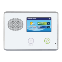
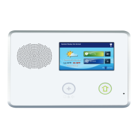
Details the functions of the control panel's sounder, display, and buttons.
Shows system status, time, date, and navigation buttons.
Provides access to Arm, Menu, and Status screens with alert indicators.
Allows arming in Stay/Away modes with options for delays.
Displays current system status and a scrolling list of alerts.
Explains how the system monitors and displays open/closed sensor conditions.
Covers methods for bypassing sensors, including force and manual options.
Details arming in Stay mode, including entry delays and quick exit.
Details arming in Away mode, including delays and silent control.
Procedures for disarming the system from Stay or Away modes.
Explains system behavior and alarm memory for burglary events.
Instructions for arming and disarming the system using a wireless key fob.
How to activate emergency alarms and auxiliary output via key fob.
Instructions for arming and disarming the system using a wireless keypad.
How to activate fire or police alarms using a wireless keypad.
Covers automatic alarms, manual initiation, and silencing false alarms.
Explains the availability and use of Panic, Fire, and Emergency buttons.
Details the specific functions of Panic, Fire, and Emergency buttons.
How to display and review active trouble alerts on the system.
Visual indicators for system conditions like power, battery, and connectivity.
How to display, read, and manage messages from the Central Station.
Details how to control the system remotely via telephone.
Manages user codes, schedules, and access options.
Log of system events, including arms, disarms, and bypasses.
Procedures for testing sensors, panel, and communication links.
Controls display brightness, volume, backlight, and screen cleaning.
Configures the system's clock and calendar.
Access dealer contact info and request service callbacks.
Sets siren run time, entry/exit delays, and fire horn run time.
Configures Panic, Fire, and Emergency buttons on the panel.
Options for quick arming, bypassing, auto stay, and key fob functions.
Configures dialer delay, abort window, and voice communication.
Space for installer to log user codes and sensor zones.
Recommends setting up regular service with an alarm installer.
Compliance notices for wireless devices, FCC, and telephone rules.
Outlines potential system failures and limitations in protection.
Details the one-year warranty for material and workmanship defects.
| Z-Wave Frequency | 908.42 MHz |
|---|---|
| User Codes | 48 |
| Partitions | 2 |
| Two-Way Voice | Yes |
| Connectivity | Wi-Fi, Ethernet |
| Compatibility | 2GIG |
| Battery Life | 24 Hours |
| Alarm Output | Built-in siren |
| Communication | Cellular |
| Power Supply | AC power with backup battery |