Do you have a question about the 2gig Technologies Go Control and is the answer not in the manual?
Recommended temperature ranges for control panel operation and storage.
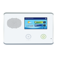
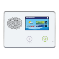
Sounds alarms, voice prompts, and audio for 2-way communication.
Shows system info, status, programming, and functions via touch interface.
Used for voice communication with the Central Station.
Indicates emergency alarms and flashes during them.
Shows sensor and arming status, power outage indicators.
7.2 Volt Ni-mh battery pack included with the Control Panel.
Used for RJ45 connection to installation's RJ31X telephone jack.
Connections for power, solid state output, bell, and hardwire loops.
Alternate connection for power (plug-in barrel connector).
Connector for firmware update cable.
Module for over-the-air communication with Central Station.
345 MHz receiver for wireless sensors.
For connecting lineman's "buttset" for monitoring telephone line.
Hooks onto mounting plate during installation.
Lists optional system components like Cell Radio Module and antennas.
Lists types of wireless sensors supported by the system.
Guidelines for placing the control panel for best sensor signal reception.
Instructions for attaching the mounting plate to the wall.
General guidance for installing wireless sensors.
Diagrams showing different hardwire loop configurations (N.C., N.O., EOLR).
Information on connecting an optional remote alarm sounder.
Details on the programmable solid-state output for activating devices.
Steps for connecting wiring to the control panel's terminal block.
Table showing maximum wire lengths for different gauges.
Steps for connecting the power supply and mounting the panel.
Guidelines for commercial installations, noting limitations for fire protection.
Describes the main screen showing system status and basic controls.
Details the screen for accessing arming, menu, and status functions.
Explains options for arming the system (Stay, Away, Entry Delay, Silent Exit).
Shows system status and provides access to Arm, Toolbox, and emergency features.
Lists system status and any alerts, with an option to silence announcements.
Explains how to enter the installer code to access the toolbox.
Entry point for programming system settings, starting with RF sensor configuration.
Explains the use of directional arrows and the Go To button for navigation.
How to navigate questions with multiple selectable options.
How to enter data, including text, using the keypad and vocabulary.
Describes the function of buttons like Esc, Sum, End, Learn, Paste, and Exit.
Process of enrolling the control panel with the Central Station.
Explains the options available for programming each RF sensor.
Assigning a sensor type (zone) to a programmed sensor.
Selecting the equipment type for certain sensor types.
Assigning a 4-digit code for the sensor model.
Manually entering or learning the sensor's serial number.
Setting whether the sensor is new or existing.
Assigning loop numbers for sensors with multiple inputs.
Setting delayed or immediate dialing for sensor reports.
Assigning voice descriptors for sensor annunciation.
Enabling or disabling reports to the Central Station.
Enabling or disabling sensor supervision for trouble alerts.
Introduction to programming wired sensors.
Steps for programming wired sensors.
Assigning a sensor type (zone) to a wired sensor.
Selecting equipment type for certain wired sensor types.
Assigning a 4-digit code for the wired sensor model.
Setting whether the wired sensor is new or existing.
Setting delayed or immediate dialing for wired sensor reports.
Assigning voice descriptors for wired sensor annunciation.
Enabling or disabling reports to the Central Station.
Setting chime options for wired sensors.
Detailed configuration settings for each RF Key Fob.
Enabling or disabling the key fob.
Assigning the key fob model code.
Entering special codes for non-standard key fobs.
Manually entering or learning the fob's serial number.
Setting whether the fob is new or existing.
Configuring the emergency key function.
Allowing or preventing the key fob from disarming the system.
Assigning voice descriptors for fob annunciation.
Configuring instant arming without an exit delay.
Selecting action for the key fob's auxiliary button.
Detailed configuration settings for each RF Keypad.
Enabling or disabling the keypad.
Assigning the keypad model code.
Entering special codes for non-standard keypads.
Manually entering or learning the keypad's serial number.
Setting whether the keypad is new or existing.
Enabling or disabling keypad emergency keys.
Assigning voice descriptors for keypad annunciation.
Setting the exit delay time for arming the system.
Setting the first entry delay time.
Setting the second entry delay time.
Enabling or disabling the digital communicator (dialer).
Entering a prefix for PBX systems to acquire dial tone.
Entering code to disable call waiting during communication.
Entering the primary Central Station phone number.
Entering the primary Central Station account number.
Enabling 2-way voice communication with the Central Station.
Enabling audio listen-in for silent panic or burglary alarms.
Selecting between touch tone or rotary dialing.
Configuring the action of the police emergency button.
Enabling or disabling the fire emergency button.
Enabling or disabling the general emergency button.
Allowing system arming without a user code.
Setting the maximum alarms per sensor during arming.
Supervising the external sounder wiring connection.
Setting the period of inactivity before notification.
Setting the time to trigger a trouble condition for cell radio failure.
Enabling or disabling trouble indications for cell radio failure.
Enabling or disabling reports for cell radio failure.
Automatically arming in Stay Mode if no exit/entry sensor is violated.
Allowing re-entry to restart the exit delay.
Enabling a quick exit button for faster arming.
Setting the interval for automatic test reports.
Setting the time window for sending a cancel report after an alarm.
Enabling or disabling the display of cancel reports.
Enabling cross-sensor verification for alarms.
Setting the timeout for cross-sensor verification.
Setting delay for dialer to allow false alarm cancellation.
Setting how long the bell sounds for burglary alarms.
Setting how long the bell sounds for fire alarms.
Setting the delay before displaying an AC power loss alert.
Enabling random reporting times for AC power status.
Entering the secondary Central Station phone number.
Entering the secondary Central Station account number.
Controlling remote access mode (data, voice, or both).
Setting or changing the installer access code.
Limiting installer access to programming after a set period.
Controlling the ability to reset the panel to factory defaults.
Suppressing trouble beeps during nighttime hours.
Delaying re-sounding of trouble beeps for fire/CO sensors.
Entering the CSID code for remote programming verification.
Reporting installer entry/exit from programming mode.
Enabling or disabling reports for sensor trouble conditions.
Enabling or disabling reports for manual sensor bypasses.
Enabling or disabling reports for AC power loss.
Enabling or disabling reports for control panel low battery.
Enabling or disabling reports for RF sensor low battery.
Enabling or disabling reports when the system is disarmed.
Enabling or disabling reports when the system is armed.
Enabling or disabling reports when an alarm is restored.
Enabling or disabling reports when a trouble condition clears.
Enabling or disabling reports when a bypassed sensor is restored.
Enabling or disabling reports when AC power is restored.
Enabling or disabling reports for control panel low battery restoration.
Enabling or disabling reports for RF sensor low battery restoration.
Enabling detection of telephone line failure.
Enabling or disabling smart test reports to reduce Central Station traffic.
Enabling detection of RF jamming and reporting as trouble.
Enabling automatic adjustment for daylight saving time.
Setting the month for daylight saving to start.
Setting the week for daylight saving to start.
Setting the month for daylight saving to end.
Setting the week for daylight saving to end.
Configuring tamper switch to cause trouble or alarm.
Allowing bypass of open sensors without a code.
Enabling unique sound for disarming after an alarm with a key fob.
Enabling unique sounds for key fob arming/disarming.
Automatically removing manual bypasses upon system disarm.
Reporting sensors that were force bypassed.
Filtering events recorded in the system's event log.
Configuring the open collector output activation based on system events.
Enabling or disabling the Z-Wave home services feature.
Enabling or disabling the Z-Wave switches button.
Enabling or disabling the Z-Wave thermostats button.
Enabling or disabling the Z-Wave door locks button.
Selecting display units (Fahrenheit or Celsius) for Z-Wave thermostats.
Requiring the master code to access services and Z-Wave configurations.
Setting master user or installer code access to Z-Wave toolbox.
Shutting off the siren after a two-way audio session.
Configuring how the system reacts to remote arming with open sensors.
Selecting which alarm types activate a Z-Wave siren.
Enabling the "always on" backlight option for demo mode.
Saving programmed changes and exiting configuration.
Accessing the User Toolbox for system customization.
Setting up user codes, including the duress code.
Adjusting display brightness and timeout settings.
Performing system tests to ensure proper operation.
Option to temporarily disable or enable the sounder during testing.
Verifying that the Central Station receives reports from each zone.
Displays signal strength for sensors to aid in placement.
Step-by-step guide for performing a sensor walk test.
Checking the status and signal strength of the Cell Radio Module.
Performing a test to check the cell radio's connection and status.
Checking the land-line connection to the Central Station.
Method to selectively reset programming values to defaults.
Limitations and considerations for wireless signaling devices.
Radio frequency energy usage and potential interference guidelines.
FCC requirements for alarm dialer systems and dialing attempts.
Notices regarding Industry Canada certification and telephone connections.
Important notes for commercial installations under UL standards.
Recommended temperature ranges for control panel use and storage.
| Alarm.com Compatibility | Yes |
|---|---|
| Warranty | 1-Year Limited Warranty |
| Display | Touchscreen LCD |
| Power Supply | AC Power Adapter |
| Communication | Cellular, Wi-Fi (optional) |
| Battery Life | Up to 24 hours (backup battery) |
| Remote Control | Via Alarm.com app |
| Voice Control | Yes, with Amazon Alexa and Google Assistant |
| Installation | Professional or DIY |