Installation Outline
©2013 2GIG Technologies Inc. All Rights Reserved.
15
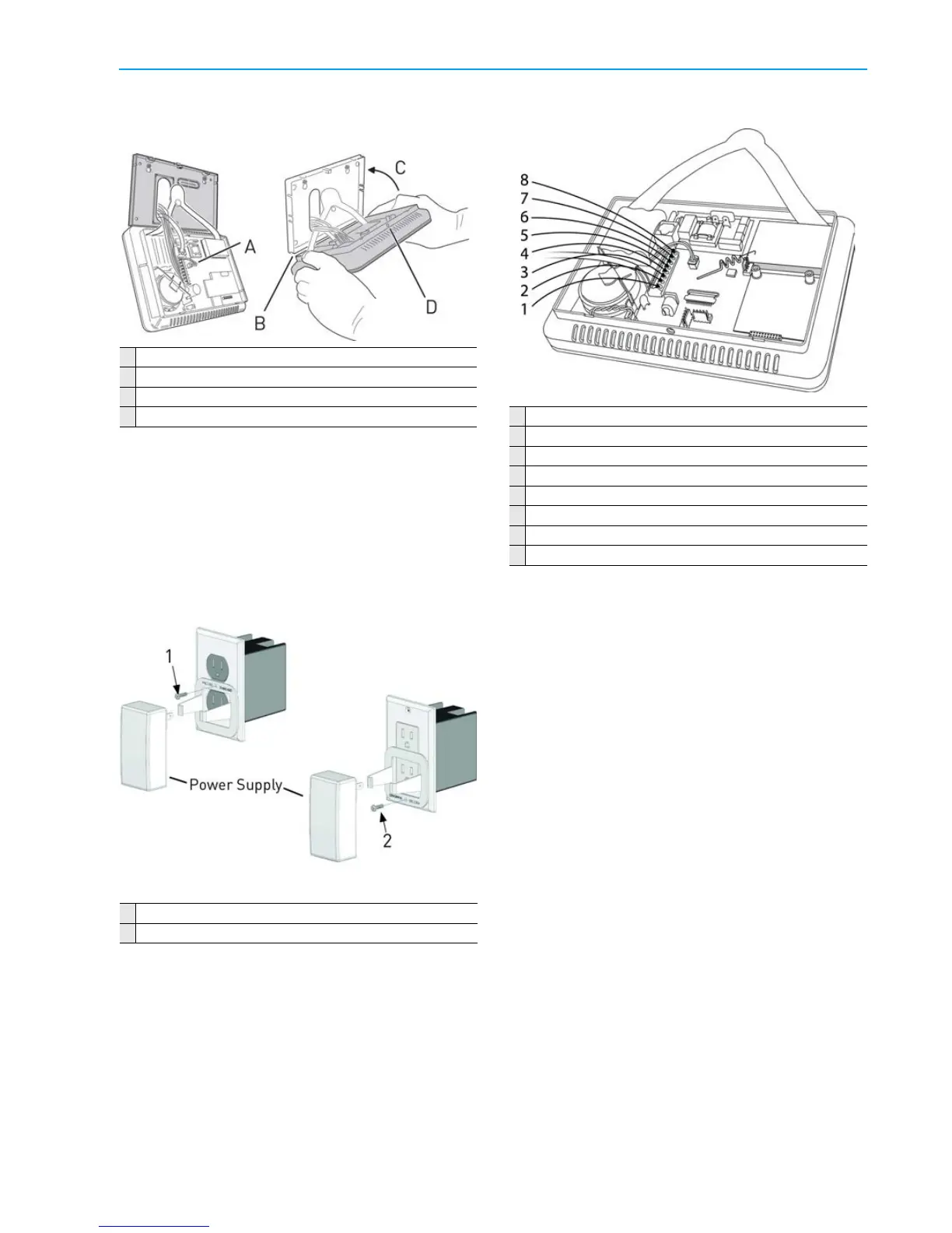
2 Peelofftheadhesivebackingfromthepower
supplyretainingbracketandattachthe
brackettotheoutletwithawallplatescrew.
A Connectbattery
B Alignmountingplateinsideofconsolebottomedge
C Swingconsoleupandsnapintothemountingplate
D Secureconsolewithscrewinretaininghole
3 Spreadtheretainingbracketearsandplugthe
ControlPanel’ spowersupplyintotheun‐
switchedoutlet.Slotsareprovidedonthe
brackettosecurethepowersupplywithazip‐
tie.
4 Afterabout5seconds,theControlPanel
indicatesthatpowerhasbeenapplied.Ifthe
ControlPaneldoesnotpowerup,checkthe
powersupplypolarity.
1
Placethescrewhereforabracketonastandardstyleoutlet.
2
Placethescrewhereforabracketonadecorastyleoutlet.
NOTE: Usethepowersupplyretainingbracket
intheUnitedStates(andothercountries
whereitisrequired).Canadadoesnot
requirethe powersupplyretaining
bracket.
Terminal Block Wiring Diagram
1 +14VDC
2 ‐14VDC
3 GND
4 OpenCollector
5 +Bell
6 ‐Bell
7 Hardwire1
8 Hardwire2
RECOMMENDED COMMERCIAL
INSTALLATIONS
Securitysystemsinstalledinacommerciallocation
areforuseonlyasaburglaralarmsystemandnot
forfireprotection.
NOTE: Thissecuritysystemisincompliance
withUL681(BurglarandHoldupAlarm
Systems)andUL827(CentralStation
AlarmServices).
NOTE: Allentriesandexitswithina
commercialinstallationsetupmustbe
protectedaccordingtoUL681(Burglar
andHoldupAlarmSystems).
Strandedc
onductorsclamped
underwire‐binding
screwsorsimilarpartsshallhavetheindividual
strandssolderedtogetherorarrangedina
constructionthathasbeendeterminedtobethe
equivalent.Notethatinternationalrequirements
donotallowstrandedconductorstobesoldered
togetheriftheyaretobeclampedbecauseofcold
fl
owofthesolder
.Anapprovedtypecrimp
connectormustbeusedorbareconductors
themselvesmustbeinspectedtoensurethatthere
arenostraywirestrands.
See"CommercialRegulatoryListings"onpage62.