Installation Outline
©2013 2GIG Technologies Inc. All Rights Reserved.
13
4 Atthedemarcationbox,connecttheBlack
cablewiretothehousetelephoneRingwire(s),
andtheYellowcablewiretothehouse
telephoneTipwire(s).
5 AttheControlPanel,connectthecable’sRed
wiretotheRJ31Xjack’sRinginterminal,and
theGreenwiretotheRJ31Xjack’sTipin
terminal.
6 AttheControlPanel,connectthecable’sBlack
wiretotheRJ31Xjack’sRingoutterminal,and
theYellowwiretotheRJ31Xjack’sTipout
terminal.
7 Snapthecoveronthejack.Plugoneendofthe
modularcableintothejackandslideitthrough
theholeinthemountingplateintothewall.
8 PoweruptheControlPanel.FromtheMenu
Screen,presstheToolbox/System
Configuration.Pre sstheGoTobuttontojump
directlytoQ8,Q11andQ12toprogramthe
POTSmodule.IfyoudonotprogramthePOTS
moduletheControlPanelwillneveraccessor
usethePO
TSmodule.
CELL RADIO MODULE
INSTALLATION
IfinstallingtheCellRadioModule,seebelow:
NOTE: Theroutingoftheantennawireis
critical.Routethe wireasdirectedorcell
radiointerferencewilloccur!
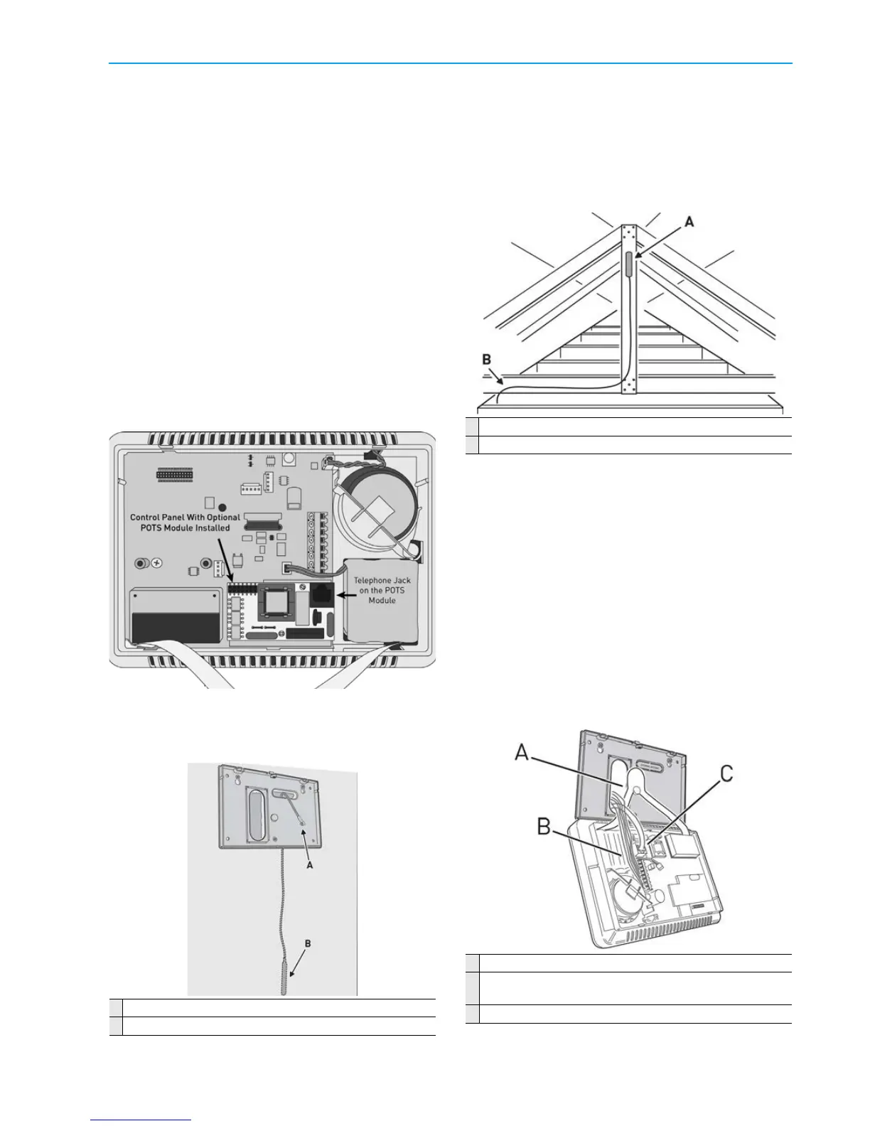
1 whenusingexternalantennas,plugthe
antennaconnectorintotheCellRadioModule.
Theantennadropsintothewallormountsin
theatticwiththecablepassingthroughthe
slotintheControlPanel’ smountingplate.
A Atticantennamountedashighaspossible
B CoaxialcabletoControlPanel
Thecellradiomoduleshouldalreadybeactivatedby
thefactory .Ifnot,contactyourserviceprovider.For
theCellRadioModuletofunction,itneedstobe
activatedbeforeitcanbeenrolled(bycreatingan
accountwiththeserviceprovider).
CONTROL PANEL WIRING
The“third‐hand”plasticstrapallowstheunitto
hangonthemountingplateduringinstallation.
1 Usingthe“thirdhand”strap,hangtheControl
Panelonthemountingplate.
2 Connectthehardwireloop,externalsounder,
andopencollectoroutputwiring(ifused)to
theControlPanel’sterminalblock.
3 Plugthetelephoneline(ifused)intothe
connectorontheControlPanel’ scircuitboard.
A Hangconsoleon“third‐hand”str ap.
B Connecthardwireloops,externalsounder,andopen
collectoroutputtoterminals.
C Plugtelephonelineintotelephonejack.
A CellRadioModuleConnector
B Endofantennahangsdowninsidethewall