12 ©2013 2GIG Technologies Inc. All Rights Reserved.
Go!Control Wireless Security System | Install Guide
NOTE: ForETLListing,anexternalDCbackup
powersupplyisrequiredforaload
connectedtoTerminal4.
NOTE: Terminal1providesDCPoweronly
whentheControlPanel’ spowersupplyis
connectedtoanACpowersource.
Thisoutputonlyfunctionswhile theControlPanel
isreceivingpowerfromthewallpowersupply.
1 Installthedevicetobecontrolledbythesolid
stateoutput.
2 Routewiringfromthedevicelocationtothe
ControlPanel’ swallcutout.
WARNING: Donotconnectan
electromechanicalbelltotheseterminals.
Damagetotheoutputwilloccur.
NOTE: Allconductorsandattachmentsare
manufacturedinaccor dancewiththe
StandardforInstallationandClassification
ofBurglarandHoldupAlarmSystems(UL
681).Commercialusersmustprovidefor
theconnectionofprotectivewiring ,
conductorsandattachments.
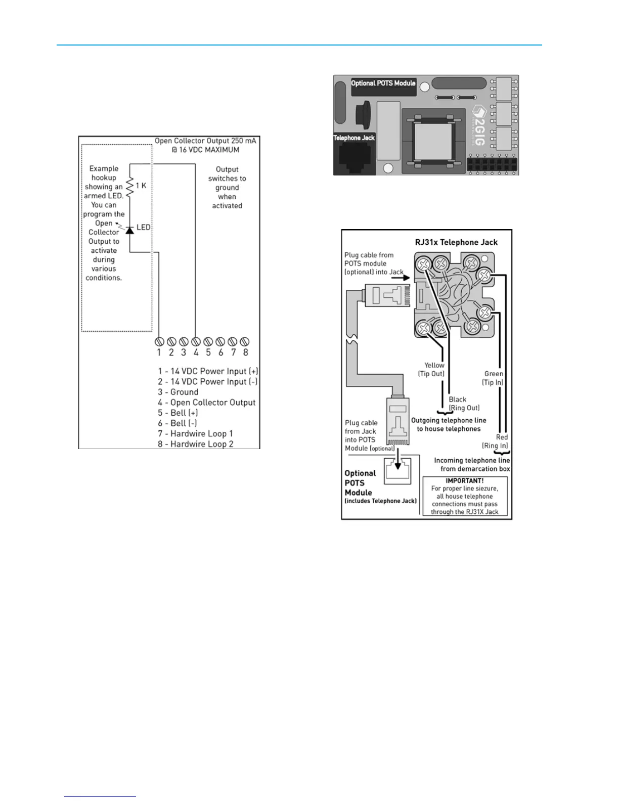
OPTIONAL TELEPHONE LINE
COMMUNICATOR (POTS)
Youcanconnectbothanincomingtelephoneline
andanoutgoingtelephonelinetothePOTSmodule.
InstallthePO TSmoduletousethetelephonejack.
Optional POTS Module
Whenthecommunicatoractivates,alllocal
telephonesaredisconnectedtopreventanoff‐hook
telephoneonthepremisesfromblockingthe
communicator’ scall
.
See"WireSizeandLength"onpage14forwire
sizeandmaximumlength.
1 Runa4‐conductortelephonecablefromthe
telephonecompanydemarcationboxtothe
ControlPanelmountingplate.Before
continuing,makesurethatyouhaveinstalled
thePOTSmoduleintotheControlPanel.
WARNING: Toreducetheriskoffire,useonly
No.26AWGorlargertelecommunication
linecordforphonelinecommunications.
2 Atthedemarcationbox,disconnectthehouse
telephonesthatarewiredtotheboxoutput.
DoNo
tdisturbthete
lcoinput“drop”sideof
theboxoranyearthgrounds.
3 Atthedemarcationbox,connecttheRedcable
wiretotheboxRing,andtheGreencablewire
totheboxTip.