©2013 2GIG Technologies Inc. All Rights Reserved. 9
INSTALLATION OUTLINE
Thefollowingoutlineisintendedtoguidethe
installingalarmdealerthroughthecomplete
installationofaGo!Controlsystem.
Usethefollowingoutlineinconjunctionwiththis
copyoftheInstallGuidetoguideyouthroughthe
installation.
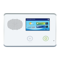
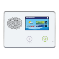
1 Unpackthesystem.Identifythesystem
components.
2 Plantheinstallationbycreatinganinstallation
floorplan.Determinethebestcentralized
locationfortheControlPanel.Decideon
wherethesensors(eitherwirelessorwiredor
both)willbeinstalled.
3 Identifyanun‐switchedwalloutletfor
plugginginthepowersupply.
4 InstalltheCellRadioModuleintotheControl
Panel.
5 IfinstallingPO TS,identifyorinstallaU.S.O.C.
RJ31Xtelephonejackforconnectionofthe
ControlPanel’ sPOTSModule(thisisoptional).
NOTE: InstallingthePOTSModuleisoptional.
6 Usethemountingplateasatemplatetomark
themountinglocationfortheControlPanel.
Markanydrywallcutoutsbehindthe
mountingplaterequiredfortheinstallation
andmakethecutouts.
7 Attachthemountingplatetothewallusing
threescrews.
8 Installeachofthesystem’swirelesssensors.If
eitherofthetwohardwireloopsaregoingto
beused,installthecontactsandroutethe
loopwiretotheControlPanel’swallcutout.
Usetheloginthe quickprogrammingguideto
documenteachsensor’sIDnumberand
location.
9 Installtheoptionalhardwiredsounder,and
routetheconnectionwiretotheControl
Panel’swallcutout.
10 Ifused,routethetelephonelinefromthe
RJ31XjacktotheControlPanel’swallcutout.
11 Forconvenience,usethe“thirdhand”strapto
hangtheControlPanelonthemountingplate.
12 ConnectallwiringtotheControlPanel’s
terminalblock.
13 IfyouinstallthePOTSModule,plugthe
telephonelineintotheContr olPanel’sPOTS
Module.
14 Plugthebackupbatteryconnectorint othe
connectoronthecircuitboard.
15 Swingthe ControlPanelup,placingthe
bottomoverthelipofthemountingbracket.
PushthetopoftheControlPanelintothe
mountingbracketuntilitsnapsintoplace,
thensecureitwiththeretainingscrew.
16 Plugthepowersupplyintotheun‐switched
walloutlet.
17 Programthesystemasdescribedinthis
manualandmarkthecheckboxesintheUser
Guidetoindicateanycustomsetuptothe
subscriber.
18 Testthesystemasdescribedinthismanual.
19 Instructthesubscriberonthesystem
operationandprovidetheUserGuidetothe
subscriber.
System Accessories
•CellRadioModule
•InternalAnt
enna
•ExternalIn‐Wal
lAntenna
•ExternalAtt
icMountAntenna
• StandardBatt
eryPack
• ExtendedBa
tteryPack
•ReplacementPowe
rSupply
Wireless System Sensors
•ThinDoor/WindowContact
• RecessedDoorCo
ntact
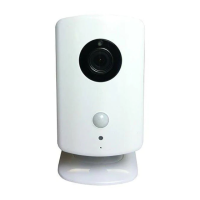
•PassiveInfr
aredMotionDetector
•4‐buttonKe
yRingRemote
•PanicButt
onRemote
•GlassBreak
Detector
•SmokeandHea
tDetector
•WirelessTou
chScreenKeypad
•WirelessKey
pad
• SuperSwitchWi
relessTakeoverModule