OSPF Configuration 153
Networking diagram
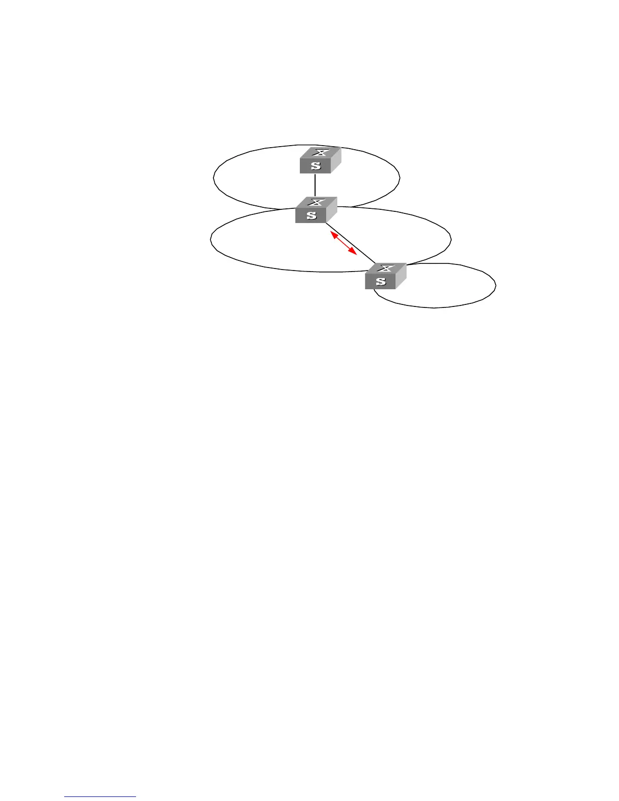
Figure 34 OSPF virtual link configuration networking
The following commands configure a virtual link between Switch B and Switch C
in Area 1.
Configuration procedure
1 Configure Switch A:
[Switch A]interface Vlan-interface 1
[Switch A-Vlan-interface1]ip address 196.1.1.1 255.255.255.0
[Switch A]router id 1.1.1.1
[Switch A]ospf
[Switch A-ospf-1]area 0
[Switch A-ospf-1-area-0.0.0.0]network 196.1.1.0 0.0.0.255
2 Configure Switch B:
[Switch B]interface vlan-interface 7
[Switch B-Vlan-interface7]ip address 196.1.1.2 255.255.255.0
[Switch B]interface vlan-interface 8
[Switch B-Vlan-interface8]ip address 197.1.1.2 255.255.255.0
[Switch B]router id 2.2.2.2
[Switch B]ospf
[Switch B-ospf-1]area 0
[Switch B-ospf-1-area-0.0.0.0]network 196.1.1.0 0.0.0.255
[Switch B-ospf-1-area-0.0.0.0]quit
[Switch B-ospf-1]area 1
[Switch B-ospf-1-area-0.0.0.1]network 197.1.1.0 0.0.0.255
[Switch B-ospf-1-area-0.0.0.1]vlink-peer 3.3.3.3
3 Configure Switch C:
[Switch C]interface Vlan-interface 1
[Switch C-Vlan-interface1]ip address 152.1.1.1 255.255.255.0
[Switch C]interface Vlan-interface 2
[Switch C-Vlan-interface2]ip address 197.1.1.1 255.255.255.0
[Switch C]router id 3.3.3.3
[Switch C]ospf
[Switch C-ospf-1]area 1
152.1.1.1/24
196.1.1.2/24
Switch A
1.1.1.1
Switch B
2.2.2.2
Virtual
Link
197.1.1.2/24
Area 2
Area 1
Area 0
Switch C
3.3.3.3
197.1.1.1/24
196.1.1.1/24