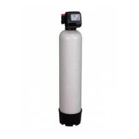
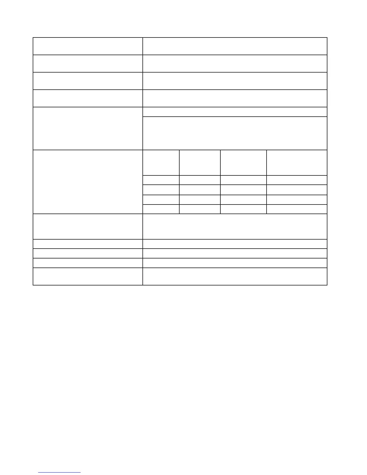
SECTION 7: VALVE SPECIFICATION AND OPERATING DATA
Maximum Service Flow Rate:
Includes Bypass Valve
27 gpm (102.2 lpm) @15 psig (103 kPa) drop
Maximum Backwash Flow Rate:
Includes Bypass Valve
27 gpm (102.2 lpm) @15 psig (103 kPa) drop
Minimum/Maximum Operating Pres-
sure:
20 psi (138 kPa) - 125 psi (862 kPa)
Minimum/Maximum Operating Tem-
perature:
40°F (4.4°C) - 110°F (43.3° C)
AC Adapter:
Supply Voltage
Supply Frequency
Output Voltage
Output Current
U.S.
120 V. AC
60 Hz
12 V. AC
500 mA
Drain Line Flow Control Unit Size Number on
Drain Line
Flow Control
Backwash Flow
Rate (gpm)
Backwash Flow
Rate (lpm)
1.0 ft
3
053 5.3 20.1
1.5 ft
3
053 5.3 20.1
2.0 ft
3
075 7.5 28.4
3.0 ft
3
100 10.0 37.9
Inlet/Outlet Tube Opening (a) 1” Universal Elbow
(b) 1” Straight brass sweat fi tting
(c) 1” Plastic male NPT fi tting
Distributor Tube Opening 1.05” OD (3/4 NPS)
Tank Thread 2 1/2”- 8 NPSM to Flanged Adapter
Control Valve Weight 4.5 lbs. (2.0 kg)
PC Board Memory Nonvolatile EEPROM
(electronic erasable programmable read only memory)
7-1
Note: After completing any valve maintenance involving the drive assembly or the drive cap assembly and pistons, unplug the power source from the
jack on the printed circuit board (black wire) and plug back in. This resets the electronics and establishes the service piston position.