12
3M™ Bair Hugger™ Warming Unit Model 775 – Service Manual
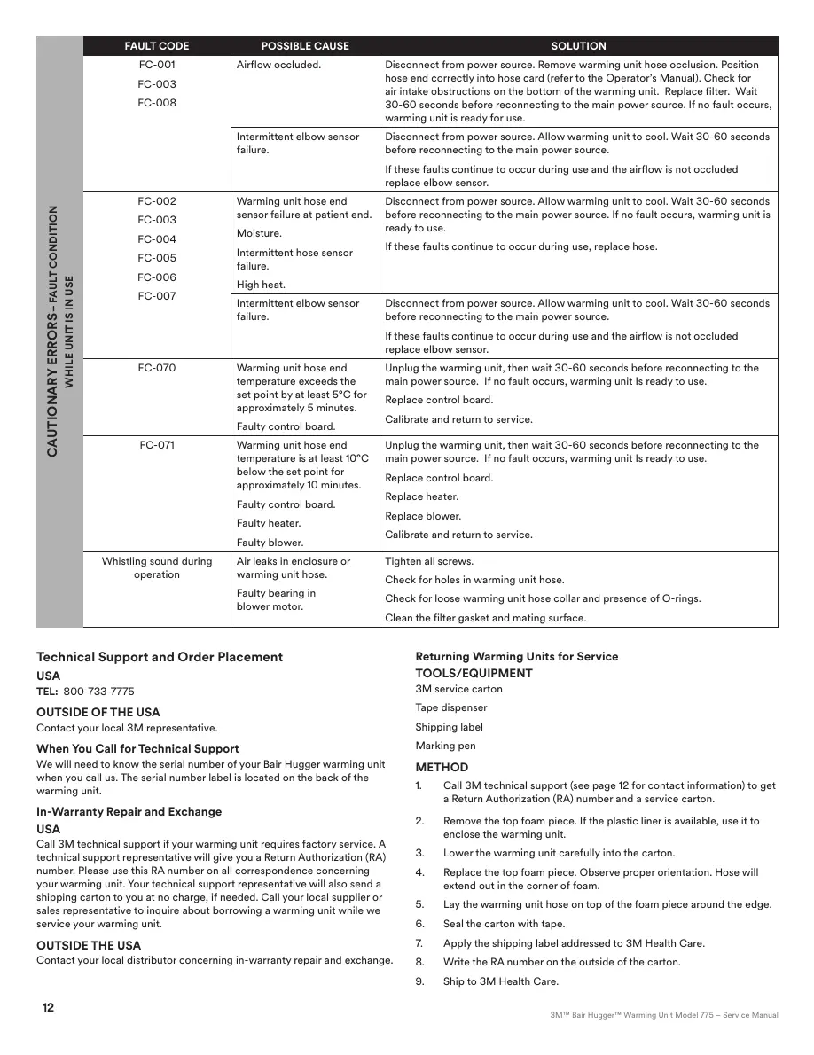
CAUTIONARY ERRORS–FAULT CONDITION
WHILE UNIT IS IN USE
FAULT CODE POSSIBLE CAUSE SOLUTION
FC-001
FC-003
FC-008
Airflow occluded. Disconnect from power source. Remove warming unit hose occlusion. Position
hose end correctly into hose card (refer to the Operator’s Manual). Check for
air intake obstructions on the bottom of the warming unit. Replace filter. Wait
30-60 seconds before reconnecting to the main power source. If no fault occurs,
warming unit is ready for use.
Intermittent elbow sensor
failure.
Disconnect from power source. Allow warming unit to cool. Wait 30-60 seconds
before reconnecting to the main power source.
If these faults continue to occur during use and the airflow is not occluded
replace elbow sensor.
FC-002
FC-003
FC-004
FC-005
FC-006
FC-007
Warming unit hose end
sensor failure at patient end.
Moisture.
Intermittent hose sensor
failure.
High heat.
Disconnect from power source. Allow warming unit to cool. Wait 30-60 seconds
before reconnecting to the main power source. If no fault occurs, warming unit is
ready to use.
If these faults continue to occur during use, replace hose.
Intermittent elbow sensor
failure.
Disconnect from power source. Allow warming unit to cool. Wait 30-60 seconds
before reconnecting to the main power source.
If these faults continue to occur during use and the airflow is not occluded
replace elbow sensor.
FC-070 Warming unit hose end
temperature exceeds the
set point by at least 5°C for
approximately 5 minutes.
Faulty control board.
Unplug the warming unit, then wait 30-60 seconds before reconnecting to the
main power source. If no fault occurs, warming unit Is ready to use.
Replace control board.
Calibrate and return to service.
FC-071 Warming unit hose end
temperature is at least 10°C
below the set point for
approximately 10 minutes.
Faulty control board.
Faulty heater.
Faulty blower.
Unplug the warming unit, then wait 30-60 seconds before reconnecting to the
main power source. If no fault occurs, warming unit Is ready to use.
Replace control board.
Replace heater.
Replace blower.
Calibrate and return to service.
Whistling sound during
operation
Air leaks in enclosure or
warming unit hose.
Faulty bearing in
blower motor.
Tighten all screws.
Check for holes in warming unit hose.
Check for loose warming unit hose collar and presence of O-rings.
Clean the filter gasket and mating surface.
Technical Support and OrderPlacement
USA
TEL: 800-733-7775
OUTSIDE OF THE USA
Contact your local 3Mrepresentative.
When You Call for TechnicalSupport
We will need to know the serial number of your BairHugger warming unit
when you call us. The serial number label is located on the back of the
warmingunit.
In‑Warranty Repair andExchange
USA
Call 3M technical support if your warming unit requires factory service. A
technical support representative will give you a Return Authorization (RA)
number. Please use this RA number on all correspondence concerning
your warming unit. Your technical support representative will also send a
shipping carton to you at no charge, if needed. Call your local supplier or
sales representative to inquire about borrowing a warming unit while we
service your warmingunit.
OUTSIDE THEUSA
Contact your local distributor concerning in-warranty repair andexchange.
Returning Warming Units forService
TOOLS/EQUIPMENT
3M servicecarton
Tape dispenser
Shippinglabel
Markingpen
METHOD
1. Call 3M technical support (see page 12for contact information) to get
a Return Authorization (RA) number and a service carton.
2. Remove the top foam piece. If the plastic liner is available, use it to
enclose the warmingunit.
3. Lower the warming unit carefully into thecarton.
4. Replace the top foam piece. Observe proper orientation. Hose will
extend out in the corner of foam.
5. Lay the warming unit hose on top of the foam piece around theedge.
6. Seal the carton withtape.
7. Apply the shipping label addressed to 3M HealthCare.
8. Write the RA number on the outside of the carton.
9. Ship to 3M HealthCare.
13
GB / 34-8718-8817-7
Specifications
Guidance and manufacturer’s declaration – electromagnetic emissions
The Model 775warming unit is intended for use in the electromagnetic environment specifiedbelow. The customer or the user of the Model
775 warming unit should assure that it is used in such an environment.
Emissions test Compliance Electromagnetic environment ‑guidance
RFemissions
CISPR 11
Group 1 The Model 775 warming unit uses RF energy only for its internal function. Therefore, its RF emissions are
very low and are not likely to cause any interference in nearby electronicequipment.
RFemissions
CISPR 11
Class B The Model 775warming unit is suitable for use in all establishments, including domestic establishments
and those directly connected to the public low-voltage power supply network that supplies buildings
used for domesticpurposes.
Harmonicemissions
IEC 61000-3-2
Class A
Voltagefluctuations/
Flickeremissions
IEC 61000-3-3
Complies
Guidance and manufacturer’s declaration – electromagnetic immunity
The Model 775warming unit is intended for use in the electromagnetic environment specifiedbelow. The customer or the user of the Model
775 warming unit should assure that it is used in such an environment.
Immunity Test IEC 60601 test level Compliance level Electromagnetic environment ‑guidance
Electrostatic
discharge(ESD)
IEC 61000-4-2
±6kV contact
±8kV air
±6kV contact
±8kV air
Floors should be wood, concrete or ceramic tile. If floors are covered with
synthetic material, the relative humidity should be at least 30%.
Electrical
fasttransient/burst
IEC 61000-4-4
±2kV for power
supplylines
±1 kV for input/output
lines
±2kV for power
supplylines
±1 kV for input/output
lines
Mains power quality should be that of a typical commercial or
hospital environment.
Surge
IEC 61000-4-5
±1 kV line toline
±2kV line(s) to earth
±1 kV line toline
±2kV line(s) to earth
Mains power quality should be that of a typical commercial or
hospital environment.
Voltage dips, short
interruptions and
voltage variations
on power supply
input lines
IEC 61000-4-11
<5% U
T
(>95% dip in U
T
)
for 0,5cycle
40% U
T
(60% dip in U
T
)
for 5cycles
70% U
T
(30% dip in U
T
)
for 25cycles
<5% U
T
(>95% dip in U
T
)
for 5sec
<5% U
T
(>95% dip in U
T
)
for 0,5cycle
40% U
T
(60% dip in U
T
)
for 5 cycles
70% U
T
(30% dip in U
T
)
for 25cycles
<5% U
T
(>95% dip in U
T
)
for 5sec
Mains power quality should be that of a typical commercial or hospital
environment. If the user of the Model 775warming unit requires continued
operation during power mains interruptions, it is recommended that the
Model 775warming unit be powered from an uninterruptible power supply
or a battery.
Power frequency
(50/60Hz)
magneticfield
IEC 61000-4-8
3 A/m 3 A/m Power frequency magnetic fields should be at levels characteristic of a
typical location in a typical commercial or hospital environment.
NOTE U
T
is the a.c. mains voltage prior to application of the test level.

 Loading...