14
3M™ Bair Hugger™ Warming Unit Model 775 – Service Manual
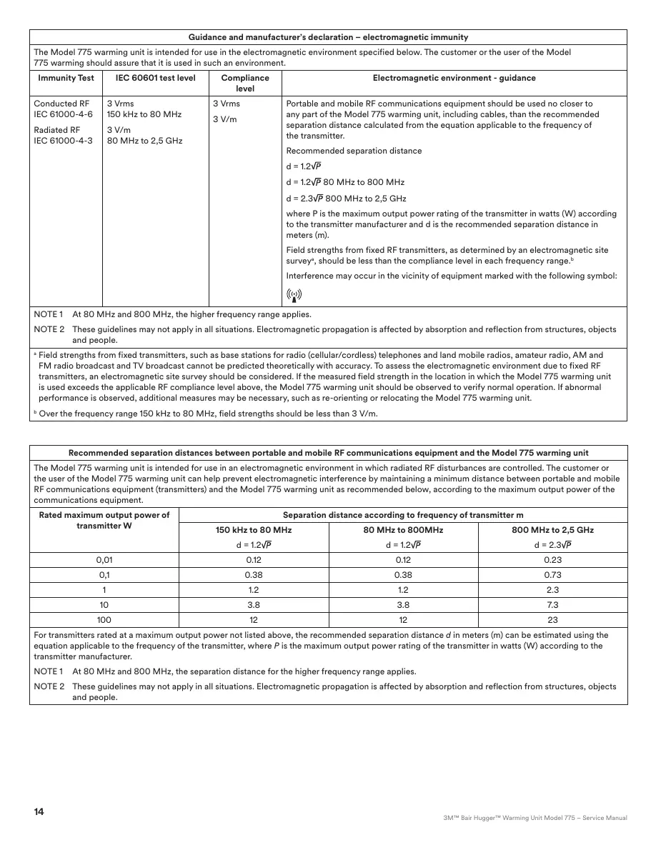
Guidance and manufacturer’s declaration – electromagnetic immunity
The Model 775warming unit is intended for use in the electromagnetic environment specified below. The customer or the user of the Model
775warming should assure that it is used in such an environment.
Immunity Test IEC 60601 test level Compliance
level
Electromagnetic environment ‑guidance
Conducted RF
IEC 61000-4-6
RadiatedRF
IEC 61000-4-3
3Vrms
150 kHz to 80 MHz
3V/m
80MHz to 2,5 GHz
3Vrms
3V/m
Portable and mobile RF communications equipment should be used no closer to
any part of the Model 775warming unit, including cables, than the recommended
separation distance calculated from the equation applicable to the frequency of
the transmitter.
Recommended separationdistance
d = 1.2
d=1.2 80 MHz to 800MHz
d=2.3
800MHz to 2,5 GHz
where P is the maximum output power rating of the transmitter in watts (W) according
to the transmitter manufacturer and d is the recommended separation distance in
meters(m).
Field strengths from fixed RF transmitters, as determined by an electromagnetic site
survey
a
, should be less than the compliance level in each frequency range.
b
Interference may occur in the vicinity of equipment marked with the following symbol:
NOTE 1 At 80 MHz and 800 MHz, the higher frequency rangeapplies.
NOTE 2 These guidelines may not apply in all situations. Electromagnetic propagation is affected by absorption and reflection from structures, objects
and people.
a
Field strengths from fixed transmitters, such as base stations for radio (cellular/cordless) telephones and land mobile radios, amateur radio, AM and
FM radio broadcast and TV broadcast cannot be predicted theoretically with accuracy. To assess the electromagnetic environment due to fixed RF
transmitters, an electromagnetic site survey should be considered. If the measured field strength in the location in which the Model 775warming unit
is used exceeds the applicable RF compliance level above, the Model 775warming unit should be observed to verify normal operation. If abnormal
performance is observed, additional measures may be necessary, such as re-orienting or relocating the Model 775warmingunit.
b
Over the frequency range 150 kHz to 80 MHz, field strengths should be less than 3V/m.
Recommended separation distancesbetween portable and mobile RF communications equipment and the Model 775 warmingunit
The Model 775warming unit is intended for use in an electromagnetic environment in which radiated RF disturbances are controlled. The customer or
the user of the Model 775warming unit can help prevent electromagnetic interference by maintaining a minimum distance between portable and mobile
RF communications equipment (transmitters) and the Model 775warming unit as recommended below, according to the maximum output power of the
communicationsequipment.
Rated maximum output power of
transmitter W
Separation distance according to frequency of transmitter m
150kHz to 80 MHz
d =1.2
80MHz to 800MHz
d = 1.2
800MHz to 2,5GHz
d =2.3
0,01 0.12 0.12 0.23
0,1 0.38 0.38 0.73
1 1.2 1.2 2.3
10 3.8 3.8 7.3
100 12 12 23
For transmitters rated at a maximum output power not listed above, the recommended separation distance d in meters (m) can be estimated using the
equation applicable to the frequency of the transmitter, where P is the maximum output power rating of the transmitter in watts (W) according to the
transmittermanufacturer.
NOTE 1 At 80 MHz and 800 MHz, the separation distance for the higher frequency rangeapplies.
NOTE 2 These guidelines may not apply in all situations. Electromagnetic propagation is affected by absorption and reflection from structures, objects
and people.
15
GB / 34-8718-8817-7
PhysicalCharacteristics
DIMENSIONS
13” high x 13” deep x 14” wide (33cm high x 33 cm deep x 36cm wide)
WEIGHT
16lb(7.3kg)
RELATIVE NOISELEVEL
53 dBA (High fan setting)
48dBA (Low fansetting)
HOSE
Flexible, compatible with the Model 241blood/fluid warmingset.
Length: 80” (203 cm)
UNIT INTAKEFILTER
MERV 14*
* See Frequently Asked Questions on Filtration (p. 58)
RECOMMENDED FILTERCHANGE
Every 12 months or 500hours ofuse
MOUNTING
Can be clamped to an IV pole, placed on a hard surface, bed rail mount, or
mounted to the rolling cartaccessory.
Temperature Characteristics
RECOMMENDED OPERATINGENVIRONMENT
TEMPERATURE:
15°C-25°C
HUMIDITY:
Max relative humidity 80% (up to 31°C) decreasing linearly to 50% relative
humidity at40°C.
ALTITUDE:
Max2,000m
TEMPERATURECONTROL
Electronicallycontrolled.
HEATGENERATED
High fansetting:
1600BTU/hr (average), 470W(average)
Low fansetting:
1330BTU/hr (average), 390 W (average)
OPERATINGTEMPERATURES
Average temperatures at the end of thehose:
HIGH: 43° ± 1.5°C (109.4° ±2.7°F)
MED: 38° ± 1.5°C (100.4° ±2.7°F)
LOW: 32° ± 1.5°C (89.6° ±2.7°F)
TIME TO REACH OPERATING TEMPERATURE
2 - 5 minutes (dependent on blanket model)
Time required for the contact surface temperature to heat up from 23 ± 2°C
to 37°C (73± 2°F to 99°F).
STORAGE/TRANSPORTTEMPERATURE
-20°C to 45°C (-4°F to 113°F)
Store all components in a cool, dry place when not in use.
SAFETY SYSTEM
THERMOSTAT
Independent electronic circuit; thermal cutoff shuts the heater
OFF to ensure hose end air remains below 46°C to 56°C; back-up
over-temperature detection at hose inlet.
ALARM SYSTEM
Over-temperature (46°C to 56°C): red Over‑temp indicator light flashes,
alarm sounds, heater and blower shut down, operating indicator lights
turn OFF, and the user can no longer adjust the warming unit using the
control panel.
FAULT:
Fault indicator light flashes, alarmsounds.
OVERCURRENT PROTECTION
Dual input fusedlines.
ElectricalCharacteristics
HEATINGELEMENT
1400WResistive
LEAKAGECURRENT
Meets UL 60601-1and IEC 60601-1 requirements.
BLOWERMOTOR
OPERATING SPEED:
4,700rpm (high fansetting)
4,100 rpm (low fansetting)
AIRFLOW:
Up to 48cfm or 23 L/s
POWERCONSUMPTION
Peak: 1550W
Average: 800W
POWER CORD
15 ft., SJT, 3cond., 13A
15 ft., SJT, 3cond., 15A
4.6m, HAR, 3cond., 10A
DEVICERATINGS
110-120VAC, 50/60Hz, 11.7 A, or
220-240 VAC, 50/60 Hz, 7.2A,or
100VAC, 50/60 Hz, 15 A
FUSES
TYPE:
Fast acting ceramic fuses, 250VAC
AMP RATING:
12 A (110 - 120VAC)
8A (220 - 240VAC)
15A (100 VAC)
OPERATING SPEED:
F (Fast Acting)
BREAKINGCAPACITY:
15A, 12A: 750A @ 250 Vac
15A, 12A: 10,000A @ 125 Vac
8A: 200A @ 250 Vac
8A: 10,000 A @ 125 Vac

 Loading...