This document is an engine manual for the 3W 342i B2 / TS model airplane engine, and also covers the 342i B4 and 342i B4 TS variants. It provides comprehensive information on installation, operation, maintenance, and troubleshooting for these gasoline-powered engines.
Function Description:
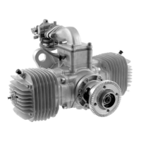
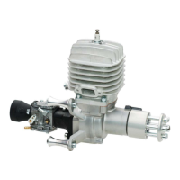
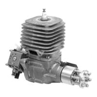
The 3W 342i B2 / TS is a high-performance, air-cooled, two-stroke gasoline engine designed for model airplanes. It is available in single and two-cylinder configurations, with the manual specifically referencing the 342i B2/TS (two-cylinder) and 342i B4/TS (four-cylinder, implied by the B4 designation and image, though the text primarily focuses on two-cylinder aspects for some specifications). The engine is designed to provide high torque in the low RPM range, excellent running characteristics, and a long operational life, making it suitable for demanding model aircraft applications. The engine incorporates an intelligent Ignition System (IIS) with a microprocessor-controlled auto-timing feature, which optimizes spark timing for easy starting and efficient operation across the RPM range. This system uses two magnets in the engine's hub and a Hall sensor to transmit signals to the microprocessor, which then adjusts ignition timing based on the engine's specific characteristics.
Important Technical Specifications:
- Cylinder Capacity: 342 ccm / 20.86 cu.in
- Power/Puissance: 32 HP / CV; 23.5 kW
- Bore Diameter/Alesage: 66 mm / 2.60 in
- Hub/Stroke/Course: 50 mm / 1.97 in
- Speed Range/Vitesse de Rotation: 1200 - 6500 min-1 / rpm
- Weight (one spark, incl. ignition): 8570 g / 19.91 lbs
- Weight (two spark, incl. ignition): 8820 g / 19.46 lbs
- Crankshaft: 3 Ball bearings / 3 Roulement à billes
- Pleuel/Connection Rod/Bielle: Needle bearings on both ends / Roulement à aiguille aux deux cotés
- Fuel/Gasoline-Version: 1:50 - 1:80 Mix, full synthetic oil, high Octane unleaded fuel (98 Octane is recommended)
- IIS - Ignition/V.cc allumage: 6.0 V
- Propeller (2-bladed): 36 x 16; 38 x 14; 40 x 12
- Propeller (3-bladed): 36 x 12; 36 x 14
- Ignition System Temperature Range: -40°C / +65°C ambient temperature
- Ignition System Voltage Range: 4.8 V - 7.5 V (five cells NICAD)
- Ignition System Open-Circuit Current: 18 mA
- Ignition System Current Consumption (0 rpm): 20 mA
- Ignition System Current Consumption (1000 rpm): 100 mA (one-cylinder), 120 mA (two-cylinder)
- Ignition System Current Consumption (6000 rpm): 950 mA (one-cylinder), 1100 mA (two-cylinder)
- Ignition System Current Consumption (10,000 rpm): 1100 mA (one-cylinder), 1300 mA (two-cylinder)
- Ignition Voltage: > 20 kV
- Max RPM: 12,000 rpm
- Magnet Red (north pole): upper dead point
- Magnet Green (south pole): 55° before upper dead point
- Normal Operating Temperature Range: 176-212 Fahrenheit (80-100 Celsius)
Usage Features:
The manual emphasizes safe operation and proper installation for optimal performance and to maintain the 36-month conditional warranty.
- Engine Installation: Requires mounting on a stiff motor box made from 1/4" (up to 106cc) or 3/8" (150cc class) aircraft plywood, ensuring a tension-free, flat, and level mounting surface to prevent crankcase distortion. Spacers for thrust adjustments should be between the motor box and fuselage, not the engine and motor box. Direct mounting onto spacers or wide formers is prohibited due to vibration and airflow issues.
- Engine Cooling: Critical for engine longevity. Requires an appropriately sized air intake and an exhaust air outlet four times the size of the intake. Baffling is highly recommended to direct cool air over the cylinder fins, ensuring turbulent airflow for maximum cooling. Special attention to cooling is needed for pusher configuration engines.
- Rear Induction: Carburetors, whether front or rear, require a steady supply of fresh air, ideally through an air scoop in the front of the plane. The fuselage interior must be sealed to prevent fuel damage.
- Ignition Placement: The electronic ignition module should be mounted away from hot air, using the supplied rubber grommets to create a 1/16" gap for cooling. The ignition timing is factory-set.
- Canister Mufflers: Require a flexible support bracket mounted at the canister's center of gravity (where 3W canisters have a reinforcement ring) to prevent header damage.
- Fuel System: Requires a minimum 4" separation between receiver components and ignition-related items. Use plastic spiral sheaths for ignition cables. The spark plug cap must be firmly seated. Use 3W-recommended ignition on/off switches and a 6V power supply for the ignition. A high-quality throttle servo is recommended. Fuel tanks should not be filled via the carburetor fuel line. Fuel lines should have small plastic cable ties, and the in-tank fuel line should be cut in half and joined with a brass tube (with soldered DUBRO barbs) to prevent kinking.
- Propellers: Only approved brands and sizes should be used. Propeller blades must be of the same length, flat (max 1/64" difference in blade height), and have identical tip shapes. Drilling requires a drill press, from the rear, using a drill guide or the propeller washer as a template. All prop bolts must tighten easily. Propeller balancing is critical.
- Carburetor Linkage: A metal bracket is provided to extend the carburetor pushrod horn, fixed with a 2.6mm machine screw and nut, then soldered. A metal or carbon fiber pushrod with plastic ball joints or clevises is recommended for consistent RPM at idle.
- Starting Procedure: Use a rubber stick, never hands or fingers. Ensure receiver and ignition batteries are charged, transmitter is on, throttle is low, and the plane is securely anchored. Close the choke, switch on ignition, flip until it "pops," turn off ignition, open choke, switch ignition back on, then flip until it starts. Warm up for at least 20 seconds. Avoid abrupt throttle opening due to high power.
- Carburetor Tuning: Use a tachometer. Never adjust needles while the engine is running. Tune the high needle (H) for maximum power, then richen it by 100-200 RPM. Let the engine idle for one minute; if RPM drops, lean the low needle (L) until a constant idle is achieved. Check for smooth transition with quick throttle advance. A properly tuned engine will run slightly rich after a cold start and normalize after about one minute.
Maintenance Features:
- Engine Break-In:
- Initial Break-In: Use a 2-stroke petroleum-based oil (preferably ashless) at a 32:1 or 30:1 mixture with high Octane unleaded fuel (98 Octane recommended) for 2-3 hours. A test stand break-in for approximately one hour is suggested, avoiding full throttle for more than ten seconds. Alternatively, run at 2000-2500 RPM for 4 hours. A smaller propeller is recommended during break-in.
- After Initial Break-In: Switch to high-grade fully synthetic 2-stroke oil, using the manufacturer's recommended gas-to-oil mixture. Continue to use high Octane unleaded fuel (98 Octane recommended). Examples of successful oils include Pennzoil (50:1), Redline (40:1), Amsoil DOMINATOR Racing Oil (50:1), and Amsoil Saber (100:1).
- Complete Break-In: The engine requires 12-20 hours of running time for the break-in process to be 100% complete.
- General Maintenance: Keep the engine clean. Use a pre-flight checklist before flying.
- Troubleshooting:
- Flooded Engine: Remove spark plug, turn engine to drain fuel.
- Starts then Stops: Low needle likely too lean; readjust. Could also indicate a dirty carburetor or faulty ignition.
- Rough Running/Vibration: Balance propeller, check ignition timing, check for air/fuel leaks, check spark plug (carbon, gap), ensure rigid motor mount, level engine mounting (tension-free crankcase), and secure engine/propeller bolts.
- Low Full Throttle RPM: Check carburetor settings, propeller size (may be too large), muffler system, for overheating, ignition timing, spark plug defect, and correct fuel/oil mixture.
- Ignition System Safety Function: An LED on the ignition module indicates its status. If the LED is on after 20 seconds of not turning the propeller, the ignition is prepared but not ready for operation. This prevents accidental starts and protects the battery. If the LED does not turn off when the propeller is turned, the Hall sensor may be disconnected or defective.
- Warranty: A 36-month conditional warranty is provided from the date of purchase, covering defective parts due to faulty material or manufacturing. It is voided by non-compliance with instructions, mishandling, unsuitable spare parts, unskilled repairs, or using unauthorized products. The warranty certificate and original receipt are required for claims.