QUESTIONS AND COMMENTS
We value you as a customer and your satisfaction with this product is important to us. If you have any comments or questions, or you find any parts of
this kit missing or defective, please contact our distributor in your country, whose address is printed on the packaging. You are also welcome to contact
ourmarketingsupportteamviaemail:infodesk@4M-IND.com,fax(852)25911566,telephone(852)28936241,orourwebsite:WWW.4M-IND.COM.
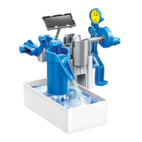
9. Align each notch with the small cutout on parts (C, I, J1, and J2) as shown in the small diagram. Insert (J2)'s 3 joints into the holes on
the pump base to secure the completed cylinder in place. Water will flow smoothly through the system only if the pieces are connected
correctly. Finally, connect the main frame to the pump base as shown.
10. Use pegs to connect the piston and small motor joint to the piston connector. The small motor joint should be inserted from the flat
side of the piston connector. Remember to lubricate the areas identified by the oil symbol.
11. Connect the small motor joint to the gearbox and then slide the piston into the cylinder.
12. Create a secure connection between the piston and cylinder connector by inserting a peg as shown. Remember to lubricate the
areas identified by the oil symbol.
13. Connect the arms, figure body and large gear joint together with a peg. Clip the legs to the figure body. Punch out two faces from
theproduct'spackagingandpushthemintothehead.
14. Insert the figurine connector into the bottom of the battery case. Slide the large gear joint onto the gearbox and figure onto the joint
connected to the battery case.
3. Insert the joint into the socket as shown.
4.Clipthesolarpanelintothebatterycase'sjoint.
Remark: The oil drop symbol indicates the areas which may require lubrication. It is recommended that you apply some cooking oil or
lotion to the joints or moving parts when assembling the product. This helps to reduce friction and enhance mechanical performance.
5. Lubricate the motor head and shaft with cooking oil or lotion before inserting it into the gearbox with the wires facing you. Place the
motorcoverovertopallowingforthewirestocomeoutofthecover'sslot.Securewithtwosmallscrews.
6.Slidethegearboxandbatterymoduleintoposition.
7. Secure two black wires in the left terminal, two blue wires in the middle terminal and three red wires in the right terminal with a
terminalcap.
8.Checkthisdiagramtoensureyouhaveconnectedthewirescorrectly.
©20194MINDUSTRIALDEVELOPMENTLIMITED.ALLRIGHTSRESERVED.