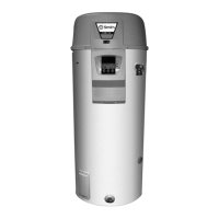
Cable colors: Components: Terminal block connections:
1 Brown A Control J2 Power connection for controller
2 Blue B Flame probe J19 Extra error signal connection
3 Yelow/Green C Hot surface igniter J20 Gas control valve connection
4 Black D Gas control valve J21 Program-controlled pump
connection
5 White E Burner earth connection
6 Grey/Beige F External ON mode switch J40 Fan connection
7 Green G Program-controlled pump
(max. 100 W)
J36 Controller display connection
JP2 Flame probe and hot surface
igniter connection
Terminal block connections: H Extra error signal connection
A
Earth J Isolating transformer JP3 Temperature sensor
T
2
connection
N Neutral K Double-pole isolator
L Live input of controller L Controller O/I switch JP4 Dummy connection
L
1
Phase input of isolating
transformer (primary side)
M Display JP5 Temperature sensor
T
1
connection
N Fan
L
2
Phase input of isolating
transformer (secondary side)
O Temperature sensor
(T
2
- bottom of tank)
JP6 Selection resistor and pressure
switch connection
L
3
Phase input of
program-controlled pump
P Dummy JP8 Extra ON mode switch connection
Q Temperature sensor
(T
1
- top of tank)
R Selection resistor F1 Fuse (T 3.15 A - 250 V)
S Push button F3 Fuse (T 3.15 A - 250 V)
T Electrical anodes
U Signaling for electrical anodes
V Potentiostat
110 Installation, Maintenance and Service part