McQuay OM 751 47
UVC Configuration Parameters
UVC Configuration Parameters
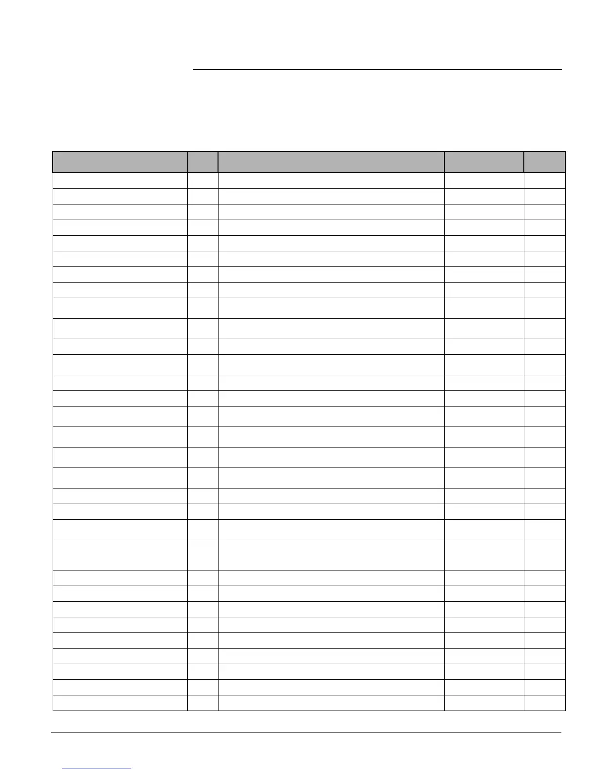
The UVC is been provided with a number of configuration variables as listed in the following
table. These configuration variables are stored in UVC non-volatile memory. For a description
of supported network variables for each protocol, refer to Protocol Data Packet bulletin ED
15065.
Table 26: UVC configuration parameters (OM 751)
Configuration Parameter Name Abr. Notes Default
LUI Menu
Item
1
Occupied Cooling Setpoint
OCS 73°F (23°C)
Co
Standby Cooling Setpoint
SCS 77°F (25°C)
C5
Unoccupied Cooling Setpoint
UCS 82°F (28°C)
CU
Occupied Heating Setpoint
OHS 70°F (21°C)
Ho
Standby Heating Setpoint
SHS 66°F (19°C)
H5
Unoccupied Heating Setpoint
UHS 61°F (16°C)
HU
Local Bypass Time Tenant override
120 min
Space CO
2
Setpoint
2
CO
2
S 1200 PPM
Space Humidity Setpoint
2
RHS
used with both active (reheat) and passive dehumidification
sequences
60% Rh
Emergency Heat Enable 0 = disable, 1 = enable (uses auxiliary heat where primary heat is
not applicable)
1
H1
Emergency Heat Setpoint
EHS 54°F (12°C)
H2
Emergency Heat Shutdown
Configuration
0 = no emergency heat during shutdown, 1 = emergency heat
available during shutdown
0
H3
Wall Sensor Type
2
0 = +/- 3°F, 1 = 55°F to 85°F
0
r5
Slave Type Configuration
2
0 = independent slave, 1 = dependent slave
0
SL
OAD Min Position High-Speed Setpoint
OADH
(this variable will be factory set to 5% open when the unit is ordered
with optional CO
2
DCV)
20% open
o2
OAD Min Position Med-Speed Setpoint
OADM
(this variable is ignored when the unit is ordered with optional CO
2
DCV)
25% open
o3
OAD Min Position Low-Speed Setpoint
OADL
(this variable is ignored when the unit is ordered with optional CO
2
DCV)
30% open
o4
Exhaust Interlock OAD Min Position
Setpoint
EOAD
OA damper minimum position when the exhaust interlock input is
energized
99% open
o5
Energize Exhaust Fan OAD Setpoint
OADE
defines position above which exhaust fan output will be energized
12% open
o6
OAD Max Position Setpoint
OAMX 99% open
o7
OAD Lockout Enable 0 = disable, 1 = enable (this variable will be factory set to 1 when
the unit is ordered as a recirc unit with no OAD)
0
o8
OAD Lockout Setpoint
OALS
OA temperature below which the OA damper will remain closed
(this variable will be factory set to –99°C when the unit is ordered
as a recirc unit with no OAD)
36°F (2°C)
o9
Economizer Enable 0 = disable, 1 = enable
1
E1
Economizer OA Temp Setpoint
ETS 68°F (20°C)
E2
Economizer IA/OA Temp Differential
ETD 2°F (1°C)
e3
Economizer OA Enthalpy Setpoint
EES 25 btu/lb (58 kJ/kg)
e5
Economizer IA/OA Enthalpy Differential
EED 1.3 btu/lb (3 kJ/kg)
e6
External BI-3 Configuration 0 = Ventilation Lockout, 1 = Exhaust Interlock
0
B3
External BO-3 Configuration 0 = Exhaust Fan On/Off, 1 = Auxiliary Heat
0
B6
Filter Alarm Enable 0 = disable, 1 = enable
0
CE
Filter Change Hours Setpoint fan run hours between filter change alarms
700 hrs