...
. . . . .
iliiiiili
AALBORG
INDUSTRIES
IGNITION ELECTRODES OM5560_84#A.2
Ignition electrodes
1
Language UK
Setting of the ignition electrodes
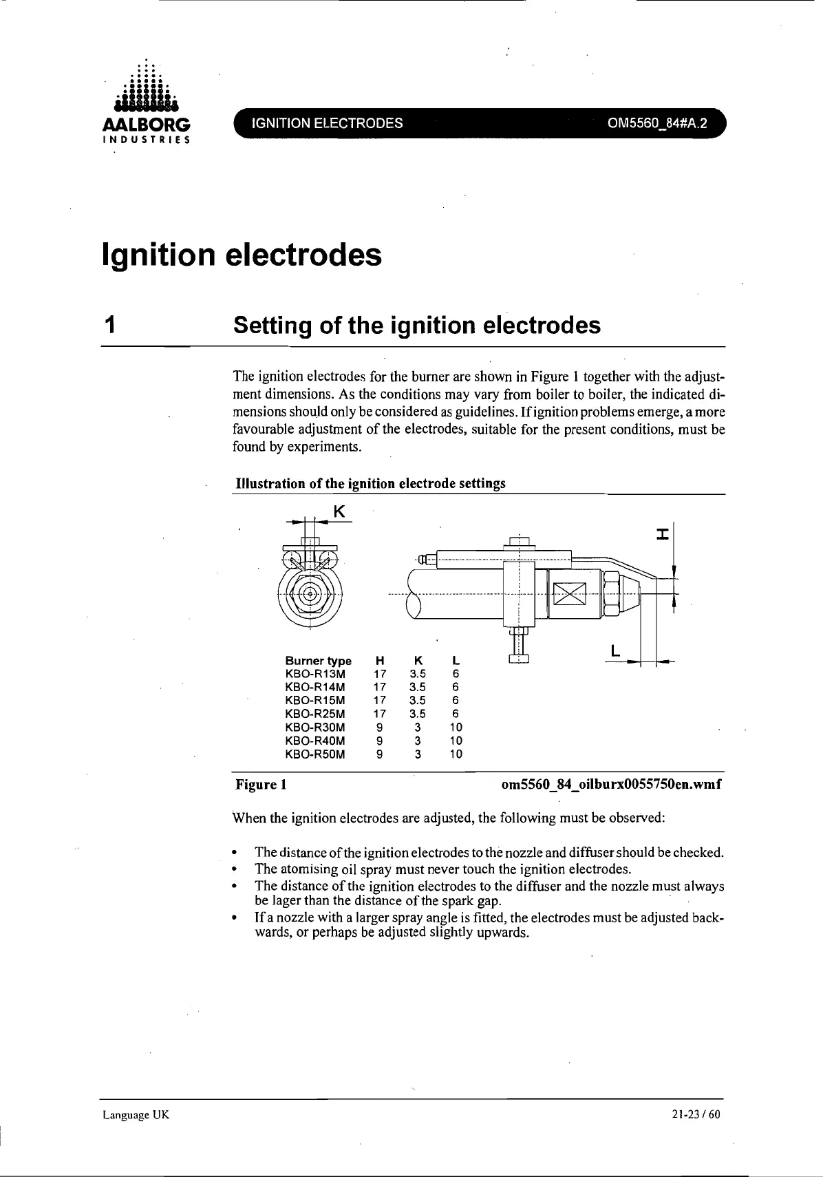
The ignition electrodes for the burner are shown in Figure 1 together with the adjust-
ment dimensions. As the conditions may vary from boiler to boiler, the indicated di-
mensions should only be considered
as
guidelines. Ifignition problems emerge, a more
favourable adjustment
of
the electrodes, suitable for the present conditions, must be
found by experiments.
Illustration
ofthe
ignition electrode settings
K
::c
...
~.--
..
_.
···_·ll--+--l--
Burner
type
H
K L
L
KBO-R13M 17 3.5 6
KBO-R14M 17 3.5 6
KBO-R15M 17 3.5 6
KBO-R25M 17 3.5 6
KBO-R30M
9 3
10
KBO-R40M
9 3
10
KBO-R50M
9
3
10
Figure 1
om5560_84_oilburx0055750en.wmf
When the ignition electrodes are adjusted, the following must be observed:
• The distance
of
the ignition electrodes to the nozzle and diffuser should be checked.
• The atomising oil spray must never touch the ignition electrodes.
• The distance
of
the ignition electrodes to the diffuser and the nozzle must always
be lager than the distance
of
the spark gap. .
•
If
a nozzle with a larger spray angle is fitted, the electrodes must be adjusted back-
wards, or perhaps be adjusted slightly upwards.
21-23/60
 Loading...