...
..
. . . .
.
,0,.
:il
..
ii
II
Ai
AALBORG
INDUSTRIES
21-38/60
I
BURNER
OPERf'TIO~
OM5560_98#A.2
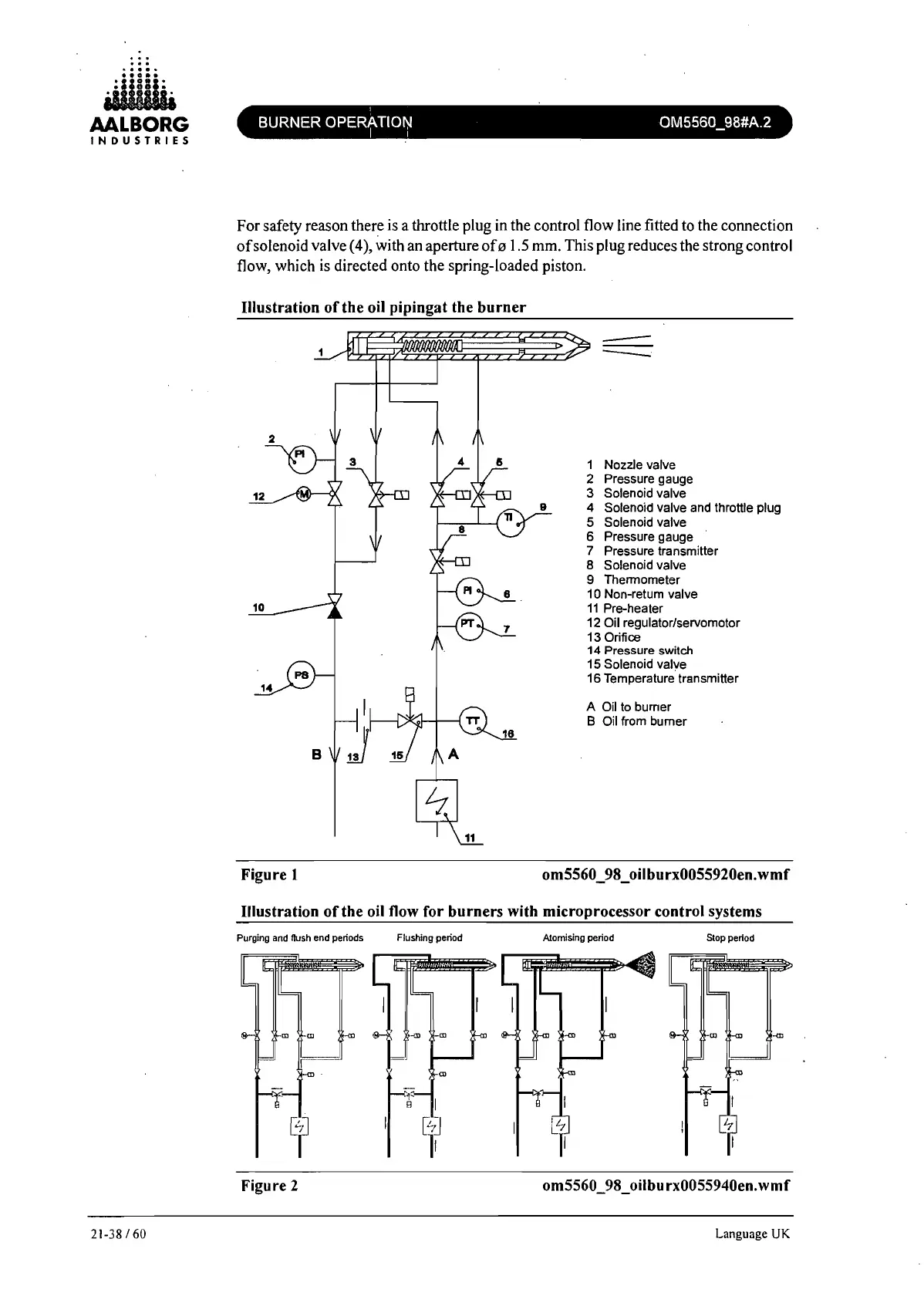
For safety reason there is a throttle plug in the control flow line fitted to the connection
of
solenoid valve (4), with an aperture
of"
1.5 mm. This plug reduces the strong control
flow, which is directed onto the spring-loaded piston.
Illustration
of
the oil pipingat the
burner
2
12
10
B
Figure 1
-
--.
1 Nozzle valve
2 Pressure gauge
3 Solenoid valve
4 Solenoid valve and throttle plug
5 Solenoid valve
6 Pressure gauge
7 Pressure transmitter
8 Solenoid valve
9 Thermometer
10 Non-return valve
11
Pre-heater
12 Oil regulator/servomotor
13 Orifice
14
Pressure
switch
15 Solenoid valve
16 Temperature transmitter
A Oil to burner
B Oil from burner
om5560 _98 _ oilburx0055920en. wm f
Illustration
of
the oil flow for burners with microprocessor control systems
Purging and flush end periods
Flushing period Atomising period
SlOp
period
Figure 2 om5560_98_oilburx0055940en.wmf
Language
UK
 Loading...