...
. . .
. . . . .
'1"1"1·::'
ii
ilii
AALBORG
INDUSTRIES
Language UK
COMMISSIONING OM5560_97#A.2
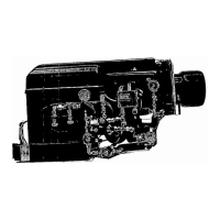
1.2 Commissioning adjustments
of
the burner
unit
On delivery from Aalborg Industries, the burner unit has been pre-adjusted to fit the
task. Even though the burner unit has been
pre~adjusted,
it
is
advisable to carry out
additional checks during commissioning. These checks are described in the following.
1.2.1 Dismantling
Step
A:
Ensure that the power is switched
off
before any work
is
carried out on the
burner unit.
Step B: Close the quick closing valves for the burner unit.
Step
C:
Unscrew the screw that holds the burner flange and swing out the burner.
Step D: Dismount the cover for the servo motors.
1.2.2 Adjustment
of
the combustion
head
Step A: Check that the distance between the oil nozzle and diffuser disc is approx-
imately 8 mm.
Step
B: Adjust the position
of
the adjustment ring in relation to the edge
of
the dif-
fuser disc according to the special instruction for this; see the chapter "Com-
bustion head".
Note:
Exact
distances
cannot
be given,
but
has to be determined when
the
burner
is
in operation.
It
is
possible to affect
the
air
velocity
and
thereby
the
shape
and
quality
ofthe
flame
by
optimising the positions
ofthe
adjustment
ring
and
diffuser disc.
1.2.3
Adjustment
of
the ignition electrodes
Step A: Check the position
of
the ignition electrodes and adjust
if
necessary. Please
see the special instruction "Ignition electrodes".
Note: An exact setting
of
the
ignition electrodes
cannot
be given,
but
has
to
be
established when
the
burner
is ignited
during
operation.
1.2.4
Adjustment
of
the servomotor
Step A: Disengage the servomotor camshaft from the drive
by
means
of
the lever
fitted to the gear box.
Step B: Calibrate the servomotor range in the control system. The low and high range
should be set to
0°
and 120° opening
of
the air dampers respectively. Set the
position
ofthe
servomotor to
0°,
which can be seen on the outer scale. The
raw data line on the control panel displays a numerical value. This value
must
be
entered in low range menu line.
Step C: Set the position
of
the servomotor to
120°.
The new numerical value, which
is
displayed
in
the raw data line, must
be
entered as the high range.
Step D: Set the time to operate the servomotor from
0°
to 120
0
on the control panel
(normally
15
seconds).
21-47/60
 Loading...