The E-BUS Digital Room Sensor is a sophisticated environmental control device designed for use with AAON's Orion Control Systems. It is available in several models, including those that sense Space Temperature only, or a combination of Space Temperature and Space Humidity. Some models feature an LCD display with buttons, while others are designed for a more discreet, no-display installation.
Function Description
The primary function of the E-BUS Digital Room Sensor is to accurately measure and display environmental conditions within a space. Depending on the model, it can sense:
- Current Space Temperature: This is a core function across all models.
- Current Space Humidity: Available in models like ASM01820 and ASM02221.
- Outdoor Air Temperature and Relative Humidity: If the connected controller is configured with an outdoor air temperature sensor, the room sensor can display these external conditions.
- Current Zone Setpoint Temperature: When the slide adjust feature is accessed, the sensor displays the current cooling and heating setpoints.
The sensor communicates with AAON's VCCX2, VCB-X, or VAV/Zone Controllers via EBC E-BUS cables. These cables are specifically designed for this purpose and should not be run in conduit with AC line voltage wiring or conductors carrying highly inductive loads to prevent interference.
Usage Features
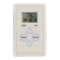
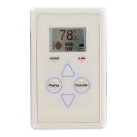
For models equipped with an LCD display and buttons (ASM01819 & ASM01820), the E-BUS Digital Room Sensor offers a rich set of user interaction features:
- Graphical LCD Display: A 112 x 64 monochrome graphical LCD with LED backlight provides clear visual feedback.
- Push Buttons: The sensor includes four main buttons:
<Display>, <Override>, <Up>, and <Down>. These buttons allow users to navigate through various screens and adjust settings. Additionally, certain functions can be accessed by touching the area below the <Display> and <Override> buttons.
- Setpoint Adjustment: Users can adjust the cooling and heating setpoints directly from the sensor's display. This adjustment is based on the controller's slide offset setpoint, allowing for a defined range of temperature modification (e.g., five degrees up or down). If the controller's slide offset setpoint is zero, this adjustment screen will not appear.
- Operation Modes Display: The LCD displays intuitive icons to indicate the current mode of operation:
- Snowflake: Cooling Mode
- Flame: Heating Mode
- Fan in Motion: Vent Mode
- Moon: Unoccupied Mode (the screen background turns dark in this mode).
- Override Functionality: An
<Override> button allows users to temporarily force the VAV/Zone Controller or VCCX2 / VCB-X Controller into Occupied Operation from an Unoccupied state. The Override LED blinks to indicate an override request and stays on for the duration of the override. Users can also cancel an active override by touching the <Override> button again.
- Unit Information Screen: This screen provides essential details about the connected controller, including its ID number, screen ID, and software version.
- Remote Sensor Connection: The sensor supports the connection of a remote 10K Ohm, Type III thermistor temperature sensor, or even a 4-sensor averaging array. This allows for temperature readings from a different location, which can be displayed on the main sensor.
LED Indicators: The sensor incorporates several LEDs to provide status information:
- Alarm LED: Blinks when there is an alarm from the Controller.
- Sense LED: Blinks when the sensor detects a valid touch.
- Override LED: Indicates the status of the override function.
- Comm LED: Located on the back of the sensor, it blinks when communications are sensed.
- Button Push LED: Indicates when a button has been pressed.
Maintenance Features
The E-BUS Digital Room Sensor includes features and guidelines to aid in its maintenance and troubleshooting:
- Sensor Configuration and Test Screens: These screens are accessible to verify sensor functionality and configure certain parameters.
- Pixel Test Screen: Allows testing the LCD display pixels by making the screen white with black characters, black with white characters, or a black or white screen.
- Sensor Info & LED Test Screen: Displays the software version running on the sensor and allows testing of the LEDs (turning them on and off).
- LCD Backlight Test Screens: Provides options to control when the LCD backlight turns on and off (always on, always off, or on with touch).
- Address Screen: Allows setting the sensor's communication address (from 1-10).
- Thermistor Averaging Screen: Enables setting the rate (1-15 seconds) at which the sensor takes new temperature readings. This feature is particularly useful for installations near frequently opened doors, allowing the sensor to average readings over a longer span for more accurate room temperature representation.
- Temperature/Resistance Testing: For the temperature-only sensor (ASM01819), a specific procedure is outlined for measuring its resistance in ohms. This test requires disconnecting the sensor from its E-BUS cable and using a meter. A provided chart correlates resistance values with ambient temperatures, allowing technicians to verify if the sensor is reading correctly.
- Remote Sensor Integration: The manual provides detailed instructions for connecting various remote temperature sensors, including a remote Standard Space Sensor or a Return Air Temperature Sensor. It also specifies modifications, such as clipping the C1 capacitor for certain remote sensor types, to ensure proper operation.
- Humidity Sensor Handling: A critical maintenance note for models with temperature and humidity sensing elements (ASM01820 & ASM02221) is a warning not to clip off or remove the temperature and humidity sensing element. This highlights the integrated nature of these components and the potential for damage if tampered with.
- Mounting Plate: An optional mounting plate is included to cover sheetrock openings, ensuring a clean installation and securing the sensor to the wall.
- Wiring Considerations: Important wiring guidelines are provided, emphasizing the use of EBC E-BUS cables and cautioning against running them with AC line voltage wiring or highly inductive loads to maintain signal integrity.
- Installation Notes: Recommendations for mounting height (at least 5 feet above the floor) and avoiding drafts or direct sunlight are given to ensure accurate readings.
- Technical Support Information: Contact details for AAON Factory Technical Support and Controls Support are provided, along with a request to have the unit's model and serial number ready when calling. Information for ordering replacement parts is also included.