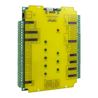
The KDH-KS3024-IP series standard controller is an access control system device designed for use with NMS ACCESS CONTROL software. Unlike integrated controllers, these standard controllers are modular units housed in a metal enclosure with a power supply, intended for installation in a protected area. Other system components, such as readers, electric locks, and buttons, are installed near the controlled door and connected to the controller. This setup enhances system security compared to integrated controllers. The controllers support various identification technologies, provided they use a Wiegand 26-40 bit interface.
The KDH-KS3024-IP model can manage either two doors in a two-way configuration or four doors in a one-way configuration. It features built-in IP ports for communication with NMS ACCESS CONTROL software and an additional RS485 port for connecting the MOD2000INOUT extension module. The system's capacity depends on the software license; a free version supports up to 8 controllers, with additional licenses required for more devices. The controller can store up to 20,000 cards in its memory. Each controller can connect to a KDH-MOD2000INOUT module, which provides 4 relay outputs, 4 inputs, and 4 transistor outputs for controlling reader buzzers.
Technical Specifications:
- Buffer Capacity:
- Card buffer: 20,000
- Event buffer: 50,000 (auto-delete of oldest)
- Alarm buffer: 20,000 (auto-delete of oldest)
- Electrical Parameters:
- Supply voltage / Current load: 12 VDC / 100 mA
- Environmental Parameters:
- Environment: For indoor installation only
- Operating temperature: -10°C to +55°C
- Relative humidity: 10% - 90%
- Physical Dimensions:
- Controller module size: 140 x 175 mm (W x L)
- Cabinet with power supply size: 350 x 304 x 91 mm (L x W x H)
- Communication Ports:
- Direct PC connection: TCP
- Extension modules connection: RS485 (dedicated port)
- Readers & Cards:
- Reader ports: 4 ports - Wiegand interface
- Card formats: 26/34 bit Wiegand, self-defined
- Card types: Compatible with reader technology
- Keypad formats on readers: 4-bits, without buffering
- Inputs:
- Door contact input: NO / NC - 4 inputs
- Exit button input: NO / NC - 4 inputs
- General inputs: NO / NC - 4 inputs
- General inputs (on extension module): NO / NC - 4 inputs (option)
- Outputs:
- Electric lock control: Relay DC 12V 3A - 4 outputs
- General output: Relay DC 12V 3A - 1 output
- General output (on extension module): Relay DC 12V 3A - 4 outputs (option)
- Access Parameters:
- Access levels: 200
- Schedules: 200
- Holidays: 80 x 64 days
- Identification mode: Card, PIN, Card or PIN, Card + PIN
- Alarm dismiss: Synchronize with input state or delay
Usage Features:
The controller supports adding cards to its memory without software, a useful feature during system commissioning and testing. Up to 3,000 cards can be added this way, granting administrator rights and 24/7 access. These cards can be remotely deleted via software later, but they are not overwritten by software-added cards. For a uniform card database, these cards should be deleted, and the database should be sent from the management software. This function is enabled by default but can be disabled via software. Adding cards via a reader only affects the database of the connected controller; for systems with multiple controllers, this procedure must be repeated for each.
Procedure for creating a programming card:
- Push and hold the "Mode" button on the controller for 3 seconds.
- Present any card to the reader; this card will become the programming card.
- To exit programming mode, press the button twice and wait 30 seconds.
Procedure for adding cards to controller memory:
- Present the programming card to the reader once. The reader's LED will blink alternately in red and green, indicating entry into programming mode.
- Present the card(s) to be added. The reader's LED will flash red for 1-2 seconds, confirming the card addition.
- To finish, present the programming card again or wait 12 seconds.
Procedure for deleting cards from controller memory:
- Present the programming card to the reader twice. The reader's LED will flash green, indicating entry into programming mode.
- Present the card(s) to be deleted. The reader's LED will flash red for 1-2 seconds, confirming the card deletion.
- To finish, present the programming card again or wait 12 seconds.
Procedure for deleting all cards from controller memory:
- Present the programming card to the reader three times. The reader's LED will flash green, indicating entry into programming mode.
- After 4 seconds, present the programming card again. All cards will be deleted, and the reader will exit programming mode.
Maintenance Features:
- Installation Guidelines: Installation should only be performed by qualified personnel. The controller must be installed indoors in a protected area with temperatures above +2°C and normal humidity. Maintain a minimum distance of 2 meters from cables and high-voltage devices, and 1 meter from telephone lines.
- Power Supply: The controller should be powered by a dedicated APSAAT4 power supply. All necessary connections must be made before connecting the controller to the power supply.
- Wiring: Wire connections and work with internal controller parts while power is on are strictly prohibited to prevent device damage.
- Housing: The controller and optional extension module should be installed in a dedicated buffer power supply housing, such as the APSAAT4, which is designed for the KDH-KS3024-IP. The housing has a 5A power supply capacity, split and protected for modules (0.9A) and locks (4A), allowing connection of the controller module, 2 or 4 readers, and 2 or 4 electric locks. The housing accommodates a 7Ah battery. For longer operation, an 18Ah rechargeable battery can be connected to the APSAAT4 battery cables, with a diode installed in series to prevent reverse charge current. Direct connection of batteries larger than 7Ah to the APSAAT4 is discouraged due to higher charging current requirements.
- Connection Steps:
- Install 4 metal spacer bars in the bottom holes of the housing.
- Connect the supply voltage output (AUX 1 12VDC) to the controller terminals.
- Connect additional terminals on the controller module supply socket to the I/O module.
- Connect the controller's RS485 port to the I/O module using a 3-core signal wire.
- Install the battery at the bottom of the housing and connect the dedicated red (+) and black (-) wires from the power supply module.
- Connect the housing tamper switch to a free alarm line input (enable monitoring schedule in software - "Always enabled").
- Connect readers, locks, buttons, and door status wires to the controller terminals.
- Connect an RJ45 cable to the Ethernet socket on the controller module, with the other end connected to the Ethernet network.
- Connect the 230 VAC mains power supply to the electrical terminal block in the bottom part of the housing (through the existing fuse), following wire color codes.
- Initial Power-Up: After all connections are made and verified, turn on the 230V mains voltage. Observe the LED indicators: 12V voltage presence indicators should light up on the power supply module, then on the controller (POWER LED) and I/O module. The RUN diode on the controller and I/O module should start blinking, followed by the LEDs on the readers.
- Housing Access: The housing features a dismantled door for easier wiring connections after disconnecting the grounding wire. It closes with two screws on the right. A tamper switch monitors the enclosure's opening, generating an alarm if not temporarily disabled by an administrator for service.