18
G
B
fig. 8
fig. 9
Please check that the air consumption and the maximum working
pressure of the pneumatic tool to be used are compatible with the
pressure set on the pressure regulator and with the amount of air
supplied by the compressor.
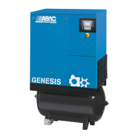
AIR RECEIVER (ON TANk-MOUNTED UNITS)
3
fig. 13
MAINTENANCE
4
PRIOR TO ANY OPERATION SET THE PRESSURE SWITCH TO THE
OFF POSITION, PULL OUT THE PLUG AND COMPLETELY DRAIN THE
RESERVOIR.
fig. 10
TABLE 1 – TIGHTENING OF HEAD TENSION RODS
Nm
Min. torque
Nm
Max. torque
Screw M6 9 11
Screw M8
Screw M10
Screw M12 76
Screw M14
(figures 11a - 11b).
API CC/SC SAE 40 API CC/SC SAE 20
fig. 12
fig. 7a
fig. 14
*
MUST BE DISPOSED OF
The compressor must be disposed in conformity with the methods
provided for by local regulations
POSSIbLE FAULTS AND RELATED PERMITTED REMEDIES
5
TABLE 2 – MAINTENANCE
FUNCTION
AFTER THE
FIRST 100
HOURS
EVERY 100
HOURS
EVERY 300
HOURS
Cleaning of intake filter and/
or substitution of filtering
element
Change of oil*
Tightening of head tension
rods
Draining tank condensate
Checking the tension of
the belts
FAULT CAUSE REMEDY
.
 Loading...