Do you have a question about the ABB ACS880-207LC and is the answer not in the manual?
Provides essential safety guidelines for handling and installing the drive unit.
Defines the intended readers and the manual's objective for installation and maintenance.
Lists and defines technical terms and abbreviations used throughout the manual.
References other relevant manuals and documentation for further information.
Explains the fundamental working principles of the IGBT supply unit.
Illustrates the basic electrical circuit configuration of the drive's rectifier.
Presents a simplified block diagram of the drive system with IGBT supply and inverter units.
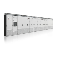
Shows a typical layout of an IGBT supply unit, illustrating cubicle arrangement.
Details the layout and components of the incoming cubicle for power connection.
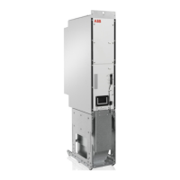
Illustrates the layout of the supply module cubicle for frame R7i.
Illustrates the layout of the supply module cubicle for frame R8i.
Shows the layout of the filter cubicle containing LCL filters.
Details the layout of the 400 mm wide auxiliary control cubicle.
Details the layout of the 600 mm wide auxiliary control cubicle.
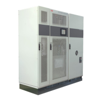
Describes the 100 kA input cubicle and its layout.
Explains the main input power and control connection points of the supply unit.
Details the control connections and interfaces of the BCU control unit.
Describes key control devices like disconnecting devices and switches for operation.
Explains the information found on the unit's type designation label.
Provides a detailed explanation of the type designation code and options.
Lists necessary tools and essential safety measures for electrical installation.
Procedures for safely disconnecting the drive from AC power sources.
Procedures for safely disconnecting the drive from a common DC bus.
Guidance on measuring insulation resistance of the drive and input power cable.
Instructions for connecting input power cables, including diagrams and procedures.
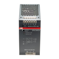
Instructions for connecting the auxiliary circuit power supply.
Guidance on verifying settings for the auxiliary voltage transformer.
Guidance on verifying settings for the cooling fan transformer.
Instructions for connecting control cables and grounding their shields.
Steps for connecting a PC to the drive for configuration and monitoring.
Procedure for installing optional modules into the control unit.
Provides general information about the BCU-x2 control unit.
Details the physical layout and terminal connections of the BCU-x2 control unit.
Shows the default input/output connections for the BCU control unit.
Instructions for connecting motor temperature sensors to the drive.
Information on the control unit's power supply connection.
Details the Safe Torque Off function and its connection terminals.
A comprehensive checklist for verifying mechanical and electrical installation before start-up.
Step-by-step guide for starting up the IGBT supply unit.
Specific instructions for closing the DC switch-disconnector in module cubicles.
Outlines maintenance tasks, schedules, and symbols used.
Procedures for cleaning the interior and exterior of the drive cabinet.
Guides for replacing AC and DC fuses in various cubicles.
Instructions for replacing cooling fans in different cubicle types.
Detailed steps for replacing supply modules in R7i and R8i frames.
Procedures for replacing capacitors and lifting inductors in LCL filters.
Instructions for replacing charging resistors.
Information on reforming and replacing DC circuit capacitors.
Description of control panel functions and status LEDs.
Guidance on operating the drive in reduced run mode.
Information on the mission time and renewal of functional safety components.
Presents electrical ratings and defines key technical parameters.
Explains derating based on ambient temperature, altitude, and coolant conditions.
Lists main circuit AC and DC fuses, including types and manufacturers.
Provides dimensional data and weight information for unit variants.
Details dimensions for various cubicle widths and input cubicle types.
Specifies torque values for electrical, mechanical, and cable lug connections.
Defines network requirements, short-circuit strength, and harmonic distortion.
Specifies environmental limits for operation, storage, and transportation.
Information on materials used, packaging, and product disposal guidelines.
Describes the components and layout of the internal liquid cooling system.
Provides guidance on connecting to standard or custom cooling units.
Step-by-step procedures for filling and bleeding the cooling circuit.
Instructions for safely draining the internal cooling circuit.
Details coolant types, specifications, and operating temperature limits.
| Control Method | Vector Control |
|---|---|
| Input Frequency | 50/60 Hz |
| Input Voltage | 380 to 690 V |
| Protection Class | IP21 |
| Rated Current (I2N) | Up to 4500 A |
| Mounting Type | Wall Mounting |
| Enclosure Class | IP21 |
| Output Current | Up to 4500 A |
| Ambient Temperature | -10 to +50 °C |
| Communication Interface | Ethernet, Profibus, DeviceNet, CANopen |
| Efficiency | Up to 98% |