B
Brittany AcostaJul 30, 2025
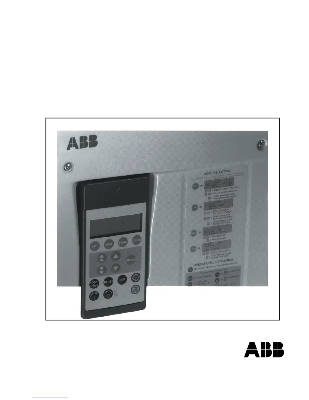
What to do if ABB Power Supply shows F 2 overcurrent error?
- BbauerchristopherJul 30, 2025
If the ABB Power Supply shows an F 2 error indicating overcurrent, you should check the motor, load, and armature cabling for faults or blocking conditions. Also, verify the parameter settings of the current control circuit/torque limitation and the parameter [P 512] for overcurrent detection.