Appendix A - Connection diagrams
DCS 500B / DCP 500B Operating Instructions IV A A - 1
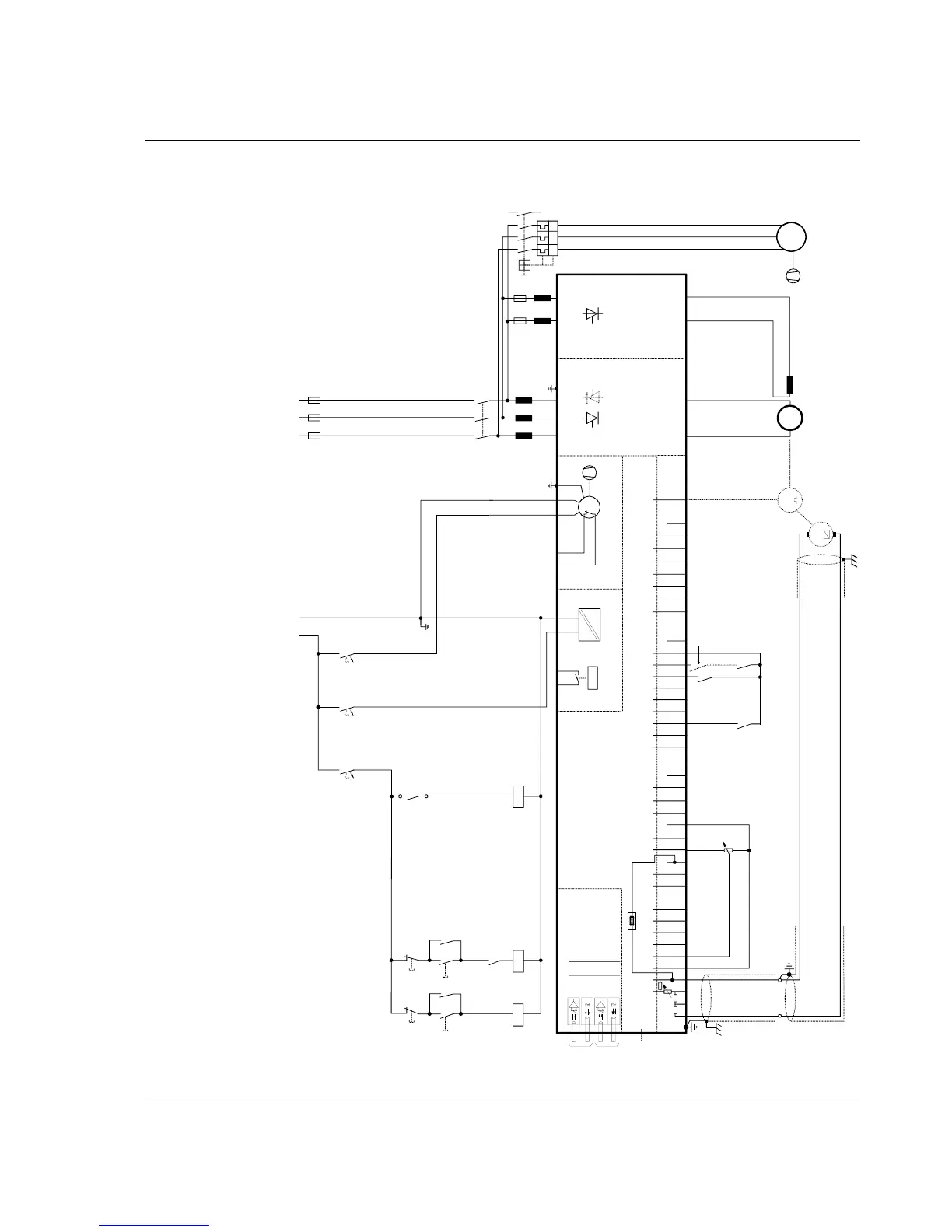
Connection diagram 1
For detailed information see
System description DCS 500B / DCF 500B.
IN3
OUT3
IN1
OUT1
V5
V6
V1
V2
X96:
DO8
12 X99:12 X2:45 X2:1 2 3
U1 W1V1 PE
K1
K20
K21K20 K1
X96:1
X96:2
L1 L2 L3
400V 50Hz
F1
F3
M
~
K21
X33
C 1 D 1
AITAC AI1
AI2 AI3
AI4
+10V -10V AO1 AO2 IACT DI1 DI2 DI3 DI4 DI5 DI6 DI7 DI8 +48V DO1 DO2 DO3 DO4 DO5 DO6 DO7
__ __
_
++++
+
T
T
M
0V
0V0V0V0V
X3: 1 2 3 4 5 6 7 8 9 10 X4: 1 2 3 4 5 6 7 8 9 10 X6: 1 2 3 4 5 6 7 8 9 10
X7:
12345678 1...10
X5:
+
_
+
_
K1
K20
K21
S4
56
F5
1
2
F8
1
2
F7
1
2
K1
135
246
L1
X1: 1 7
L3
X1: 5 3
+
_
L1 MP
230V 50Hz
2
1
4
3
6
5
F6
I > I > I >
13
14
U
V
W
M
3~
Communication
board (COM-x)
Control board (CON-2)
Power supply
(POW-1)
Converter
module
ON
OFF STOP
START
Field exciter unit
(SDCS-FEX-1/2)
depending on the unit type
an other configuration is possible
the polarities are shown for motor operation
if there are intermediate terminals
e.g. Pressure
switch at C4
module