EasyManua.ls Logo

ABB CEMcaptain GAA610-M - User Manual

ABB CEMcaptain GAA610-M
100 pages
Print Icon
To Next Page IconTo Next Page
Loading...
ABB MEASUREMENT & ANALYTICS |
OPERATING INSTRUCTION | OI/GAA610- M - EN REV. B
CEMcaptain GAA610
-M
Advanced emission gas monitoring system for marine
applications
ABB Measurement & Analytics
For your local ABB contact, visit:
www.abb.com/contacts
For more produc
t information, visit:
www.abb.com/analytical
Measurement made easy
OI/GAA610
-M-EN Rev. B 06.2021
GAA610
-M
Introduction
GAA610
-M is a multi-component analyzer system
continuously monitoring SO2/CO2 emissions of
vessels.
Reducing maintenance hassles during ship
operation has been the guiding
principle for
development. An increased uptime is provided
with the GAA610
-M by its robust and simple
design as well as its innovative digital features
allowing for tailoring services to your needs.
It is proven for use on board by all major
classificatio
n societies and complies with Marpol
Annex IV requirements and NOx Technical Code
2008.
ABB has the right gas analyzer to allow vessels to
stay compliant with current and upcoming
regulations.
Additional Information
Additional documentation on CEMcaptain GAA610-M
is available for download free of charge at
www.abb.com/analytical.
Alternatively simply scan this code:
We reserve the right to make technical changes or modify the contents of this document
without prior noti
ce. With regard to purchase orders, the agreed particulars shall prevail.
ABB does not accept any responsibility whatsoever for potential errors or possible lack of
information in this document.
We reserve all rights in this document and in the subject
matter and illustrations contained
therein. Any reproduction, disclosure to third parties or utilization of its contents
in whole
or in parts
is forbidden without prior written consent of ABB.
© ABB 2021 3KXG141006R4201

Table of Contents

Question and Answer IconNeed help?

Do you have a question about the ABB CEMcaptain GAA610-M and is the answer not in the manual?

Overview

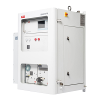
The ABB CEMcaptain GAA610-M is an advanced emission gas monitoring system designed for continuous measurement of exhaust gases from marine diesel engines. It primarily monitors SO2 and CO2 emissions, reporting the ratio as specified by the IMO (International Maritime Organization), and can also be used for continuous monitoring of CO if required. The system is based on ABB's proven NDIR (Non-Dispersive Infrared) measurement technology, specifically utilizing the AO2020-Uras26 gas analyzer module.

Function Description

The GAA610-M operates as a multi-component analyzer system, providing real-time data on relevant pollutants. It ensures compliance of vessels with low emission limits in Emission Control Areas (ECA zones) and global limits. The measurement data can also be used to control the exhaust gas cleaning system (scrubber) on board.

The system extracts sample gas from the exhaust gas stream. Since the raw sample gas cannot be processed directly due to excessive dust, temperature, dew point, or interfering components, additional devices are integrated for sample treatment. These include a sampling probe, a heated sample gas line, a sample gas cooler, filters, and a pump. These components ensure that the sample gas meets the entry conditions of the analyzer, providing accurate measurement results regardless of process and local conditions.

The GAA610-M is a complete turn-key solution, integrating all sample conditioning components and the gas analyzer into a single cabinet. Available options include an air conditioning unit for operation at ambient temperatures from 5 to 55 °C (41 to 131 °F), with higher temperatures available on request. Dual sampling for simultaneous measurement at two different locations is also an option.

The system's robust and simple design, coupled with innovative digital features, aims to reduce maintenance hassles and increase uptime during ship operation. It is proven for use on board by major classification societies and complies with Marpol Annex IV requirements and NOx Technical Code 2008.

Important Technical Specifications

  • Measuring Principle: NDIR (Non-Dispersive Infrared) technology using the AO2020-Uras26 gas analyzer.
  • Measured Components & Ranges:
    • CO2: 0 to 20 Vol.-%
    • SO2: 0 to 250 ppm or 0 to 500 ppm
    • SO2/CO2 ratio: Calculated
    • O2 (option): 0 to 25 Vol.-%
    • CO (option): 0 to 500 ppm
  • Inputs and Outputs:
    • Analog Output: 4 to 20 mA signals for measured concentrations of CO2, SO2, and SO2/CO2 ratio.
    • Digital Output: System failure/common alarm, maintenance, maintenance request, SO2 measurement range feedback. Further digital signals can be added.
  • Heated Sample Gas Line: PTFE hose, heated to 180 °C (356 °F). Temperature controlled by a Pt100 resistance thermometer and a temperature controller.
  • Sample Gas Cooler SCC-C: Defines water content at a dew point of typically 3 °C. Condensate removed by a hose pump and collected in a separate bottle. Outputs signals for condensate level and cooler fault.
  • Sample Gas Feed Unit SCC-F: Diaphragm pump for continuous sample gas feeding. Monitors flow with flow meters.
  • Backpurging Unit: Protective cabinet with shut-off valve, 6 bar pressure reduction valve, solenoid valves, pressure regulator, and a 2 L compressed air receiver.
  • Power Supply: 230 V AC, ±10%, 50/60 Hz, ±3 Hz, Single Phase NON-UPS. External fuse: 25 A.
    • System cabinet: 500 W
    • Air conditioner: 1600 W
    • Sampling probe: 300 W
    • Heated sample gas line: Approx. 90 W/m
  • Sample Gas Inlet Conditions:
    • Temperature: Max. 500 °C (932 °F)
    • Pressure: 850 to 1100 hPa (0.85 to 1.1 bar), (12.3 to 16 psi)
  • Instrument Air Supply for Backpurging: Oil-free, dry with dew point < -20 °C (-4 °F). Pressure: Min. 400 kPa (60 psig), Max. 600 kPa (90 psig). Air consumption: < 0.2 Nm³/day.
  • Climatic Conditions:
    • Operation: 5 to 55 °C (41 to 131 °F) (higher on request).
    • Transport/Storage: 2 to 60 °C (35.6 to 140 °F); -20 to 70 °C (-4 to 158 °F) after draining and drying parts in contact with condensate.
    • Humidity: Year-round average max. 75%, short-term max. 95%, occasional slight condensation permitted.
  • IP Rating: IP 54
  • Vibration Resistance: In accordance with IEC 60068-2-6.
  • Dimensions (Analyzer Cabinet): 945 (37.20) x 1600 (63.0) x 650 (25.6) mm (W x H x D).
  • Weight (Analyzer Cabinet): Approx. 240 kg (441 lb), depending on configuration.

Usage Features

  • User Interface (HMI): The system features a local operation unit with a display and control unit (LCD indicator) and can also be operated via a remote PC running 'AO-HMI' software.
  • LCD Indicator: A 320 x 240-pixel backlit graphics display divided into menu line, information field, and softkey line. Displays measurement values, status messages, and menu items.
  • Numeric Keypad: Used for numerical and text entry, including test gas concentration, date/time, air pressure, and passwords.
  • Softkeys: Six buttons under the screen with context-dependent functions for navigation and operation.
  • Password Protection: Access to calibration and configuration menus is restricted by password levels (0, 1, 2, 3) and user groups, ensuring secure operation.
  • Dynamic QR Code: A unique feature displaying dynamically generated QR codes on the display. These codes contain static system information (manufacturing number, production date, software version, serial numbers of modules) and dynamic diagnostic data (status messages, measured values, temperatures, pressures, flow rates, drift values). This facilitates improved, case-specific assistance from ABB service.
  • Automatic Back-purging: Cleans the probe filter with compressed air, controlled by the GAA610-M program. Can be time-controlled (factory-set to 12 hours), event-controlled (triggered by low sample gas flow), or manually started.
  • Automatic Calibration: Performed cyclically (daily at 7:00 am by default) using internal gas-filled cells and ambient air, without requiring external test gas.
  • Manual Calibration: Performed with certified test gases for zero and span points.
  • Language Selection: Two factory-configured languages (per order) are available, with additional languages loadable via SMT Software Migration Tool.

Maintenance Features

  • Maintenance Plan: Specifies maintenance work and intervals (daily, weekly, every 6 months, every 12 months) for various components.
  • Visual Inspection: Regular inspection of the analyzer cabinet and status LEDs for error signals.
  • Calibration:
    • Zero-point calibration: With ambient air.
    • End-point calibration: With calibration cells or test gas.
    • Basic calibration: Performed in exceptional cases (e.g., after component exchange) to reset offset and amplification drift.
    • Pressure Sensor Calibration: Performed at 'MENU / Maintenance/Test / Analyzer spec. adjustm. / Atm. press. anlz'.
  • Filter Cleaning/Replacement:
    • Ceramic filter (sampling probe): Cleaned by back-purging or replaced.
    • Oil/soot filter: Replaced (if applicable).
    • Air condition filter: Cleaned/replaced.
    • Aqua stop filter: Replaced.
    • Ambient air filter (zero gas): Replaced.
  • Hose Replacement: Hose at the hose pump from the sample gas cooler SCC-C.
  • Condenser Fin Cleaning: Condenser fins of the sample gas cooler SCC-C.
  • Diaphragm and Valve Plate Replacement: Diaphragm pump of the sample gas feed unit SCC-F.
  • Seal Integrity Check: Performed regularly (at least every 12 months) and after opening gas paths, using the pressure-drop method with a U-tube manometer.
  • Condensate Management: Emptying the condensate collection bottle when the level alarm is displayed.
  • Transportation Restraints: Instructions for activating and deactivating transportation restraints for the SCC-F and SCC-C to prevent damage during transport.
  • Troubleshooting: Detailed diagnosis and troubleshooting guide for various issues, including status messages, analyzer module problems, and air conditioner problems.
  • Spare Parts Information: Available online at www.online.abb.com.
  • Returning Devices: Procedures for returning devices for repair or recalibration, including a return form and requirements for hazardous materials.

ABB CEMcaptain GAA610-M Specifications

General IconGeneral
BrandABB
ModelCEMcaptain GAA610-M
CategoryMeasuring Instruments
LanguageEnglish

Related product manuals