IEC/EN 60947-2 Annex M
0,5
0,3
1
1,5
2
3
0,5
0,4
0,3
0,2
0,1
0,06
0
Ι∆n (A)
∆t (s)
ELR ID
R ID:
ON
FAULTALARM
TEST
off
tx10
Fault
Alarm
Ι∆nx1
Ι∆nx10
tx1
on
off
Ι∆nx0,1
FAIL SAFE
ALARM
RESET
ELR72P
8
2
5
6
7
*
ouput relays
V aux.
10
11
12
TRIPALARM
in current
test signal
current transf. TR...
1
3
9
13
14
15
16
4
ELR72P
*
Aux
321 4 5 6 7 8 9 10 11 12 13 14 15 16
ouput
relay
TRIP
ouput
relay
ALARM
V aux
input
current
remote
RESET
(auto reset)
out test
signal
T2-T1 S2-S1
234 1
ALIMENTAZIONE
TERRA
N L1 L2 L3
Ba
TR...
72
80
(con calotta)
72
102
68
68
R3
629 12
67
I
∆
x0,1
tx1
on
Fault
Alarm
I
∆
x1
I
∆
x10
tx10
off
off
A
B
C
D
E
F
ALARM
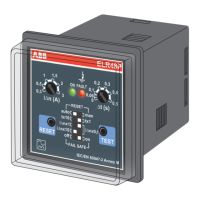
ELR72P
2CSG152424R1202
ELR72V24P
2CSG452424R1202
Relé differenziale
elettronico
da fronte quadro
Descrizione
Schema di collegamento
Programmazione Minidip
Legenda:
1) - Regolazione della sensibilità IΔn
2) - Regolazione del tempo di intervento
3) - Pulsante di test
4) - Pulsante di reset
5) - LED verde: segnalazione della presenza di alimentazione del dispositivo
6) - LED giallo: intervento del contatto di allarme
7) - LED rosso: intervento del relè
8) - Morsettiera per l’alimentazione ausiliaria e connessione del toroide
9) - Morsettiera per la connessione dei contatti in uscita
Caratteristiche tecniche Caratteristiche dimensionali (mm)
Tensione di alimentazione ausiliaria
ELR72P: 110, 230, 400 V ca (±20%); 50-60Hz
ELR72V24P: 24/48 V ca/cc (±20%); 50-60Hz
Consumo max 4 VA
0,03 ÷ 0,3 A per K = 0,1
Regolazione sensibilità IΔn 0,3 ÷ 3 A per K = 1
3 ÷ 30 A per K = 10
Regolazione tempo di intervento t
0 ÷ 0,5 sec. per K = 1
0,5 ÷ 5 sec. per K = 10
Segnalazioni led ON, led ALARM, led FAULT
Intervento contatto di allarme 60% soglia intervento IΔn (disattivabile)
Trasformatori torodali Serie TR…
Portata dei contatti in uscita 5 A 250V
Funzioni programmabili Alarm, Fail Safe, Reset da remoto, Autoreset
Temperatura di funzionamento -10 ÷ 60°C
Temperatura di stoccaggio -20 ÷ 70°C
Umidità relativa ≤ 95 %
Prova di isolamento 2,5 kV 60 sec.
Posizione di montaggio Indifferente
Tipo di collegamento Tramite morsettiera a vite (sez max cavo 2,5 mm²)
Grado di protezione
IP 52 frontale con calotta
(IP40 frontale) - IP 20 zona morsetti
Norme di riferimento CEI EN 60947-2 Annex-M
Esempio di collegamento con bobina di apertura a lancio di corrente e modalità Fail
Safe disattivata. Con utilizzo di bobina di minima tensione occorre cablare i morsetti
10-11 del contatto di fault.
A - Funzione di allarme
in posizione 1 la funzione allarme è disattivata
in posizione 0 la funzione allarme è attivata
B - Impostazione della costante di moltiplicazione del tempo di intervento
in posizione 1 K = 10
in posizione 0 K = 1
C/D - Impostazione della costante di moltiplicazione della sensibilità
con c,d in posizione 0 K = 0,1
con c in posizione 1, d in posizione 0 K = 1
con c,d in posizione 1 K = 10
E - Sicurezza positiva (Fail Safe) del contatto di Trip
in posizione 1 il relè è eccitato a riposo (sicurezza positiva, Fail Safe)
in posizione 0 il relè è diseccitato a riposo
F - Sicurezza positiva (Fail Safe) del contatto di Allarme/ Trip2
in posizione 1 il relè è eccitato a riposo (sicurezza positiva, Fail Safe)
in posizione 0 il relè è diseccitato a riposo
Minidip
1
5 6 27
3 4 8 9
PANNELLO ANTERIORE PANNELLO POSTERIORE
Alimentazione ausiliaria Vaux:
ELR72P
• morsetti 2 - 3 = 110 V ca (±20%)
•
morsetti 1 - 2 = 230 V ca (±20%)
•
morsetti 1 - 3 = 400 V ca (±20%)
ELR72V24P
• morsetti 2 - 3 = 24 V ca/cc (±20%)
• morsetti 1 - 3 = 48 V ca/cc (±20%)
Connessione al trasformatore toroidale:
- Connettere i morsetti 7 e 8 all’avvolgimento
di misura del toroide.
- Connettere i morsetti 5 e 6 all’avvolgimento
di test del toroide.
Reset da remoto / Autoreset:
-
Per realizzare il reset da remoto connettere i morsetti
15 e 16 ad un pulsante normalmente aperto.
- Per realizzare la funzione di reset automatico
cortocircuitare i morsetti 15 e 16.
TERRA
ALIMENTAZIONE
BOBINA A
LANCIO DI
CORRENTE
2CSG444008D5101