IEC/EN 60947-2 Annex M
0,5
0,3
1
1,5
2
3
0,5
0,4
0,3
0,2
0,1
0,06
0
Ι∆n (A)
∆t (s)
ELR ID
R ID:
ON
FAULTALARM
TEST
off
tx10
Fault
Alarm
Ι∆nx1
Ι∆nx10
tx1
on
off
Ι∆nx0,1
FAIL SAFE
ALARM
RESET
ELR72P
8
2
5
6
7
*
ouput relays
V aux.
10
11
12
TRIPALARM
in current
test signal
current transf. TR...
1
3
9
13
14
15
16
4
I
∆
x0,1
tx1
on
Fault
Alarm
I
∆
x1
I
∆
x10
tx10
off
off
A
B
C
D
E
F
ALARM
72
80
(with cover)
72
102
68
68
R3
629 12
67
ELR72P
*
Aux
321 4 5 6 7 8 9 10 11 12 13 14 15 16
ouput
relay
TRIP
ouput
relay
ALARM
V aux
input
current
remote
RESET
(auto reset)
out test
signal
T2-T1 S2-S1
234 1
ALIMENTAZIONE
TERRA
N L1 L2 L3
Ba
TR...
ELR72P
2CSG152424R1202
ELR72V24P
2CSG452424R1202
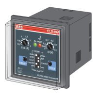
Front panel
residual
current relay
A Type
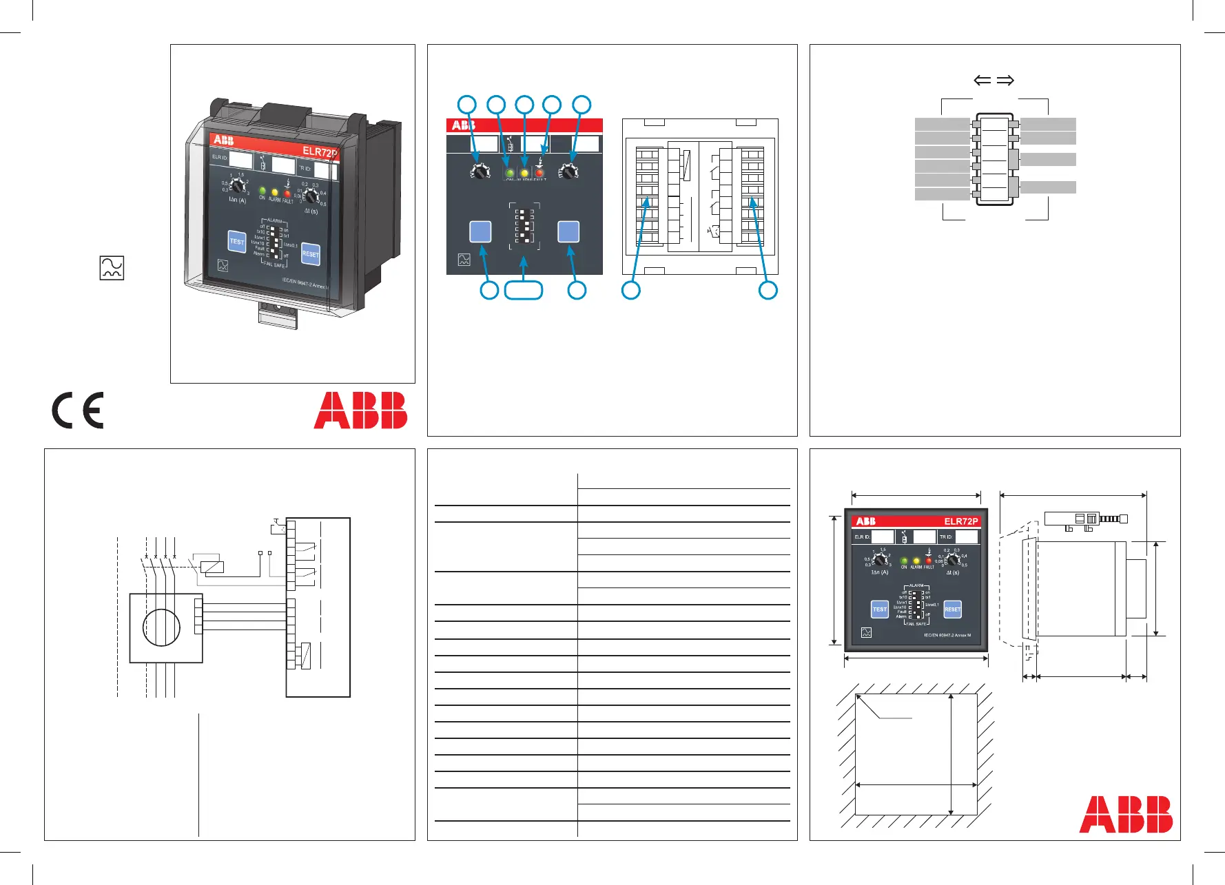
Legenda:
1) - Sensitivity setting IΔn
2) - Delay time setting
3) - Test pushbutton
4) - Reset pushbutton
5) - GREEN Led: auxiliary supply presence
6) - YELLOW Led: alarm contact intervention
7) - RED Led: trip contact intervention
8) - Terminals for auxiliary supply and toroidal connection
9) - Terminals for output contacts connection
Auxiliary Power Supply
ELR72P: 110, 230, 400 V ac (±20%); 50-60 Hz
ELR72V24P: 24-48 V ac/dc (±20%); 50-60 Hz
Maximum consumption 4 VA
0,03 ÷ 0,3 A with K = 0,1
Sensitivity setting IΔn 0,3 ÷ 3 A with K = 1
3 ÷ 30 A with K = 10
Delay time setting
0 ÷ 0,5 sec. with K = 1
0,5 ÷ 5 sec. with K = 10
Signallings led ON, led ALARM, led FAULT
Alarm contact intervention 60% IΔn set
Toroidal transformers TR range
Output contact capacity 5 A 250V
Adjustable features Autoreset, Alarm, Fail Safe, Remote reset
Operating temperature -10 ÷ 60°C
Storage temperature -20 ÷ 70°C
Max humidity ≤ 95 %
Dielectric test 2,5 kV 60 sec.
Mounting position Any
Wiring type Screw terminals/ cross section cables 2,5mm²
Protection degree
IP52 frontal with cover
(IP40 frontal) - IP20 terminals
Standard IEC EN 60947-2 Annex-M
Wiring diagram with shunt trip and Fail Safe OFF
Connect the terminals 10 and 11 when undervoltage release is used.
A - Alarm function
position 1: Alarm is OFF
position 0: Alarm is ON
B - Delay time multiplication constant
position 1: K = 10
position 0: K = 1
C/D - Sensitivity multiplication constant
c,d in position 0: K = 0,1
c in position 1, d in position 0: K = 1
c,d in position 1 K = 10
E - Fail Safe (Trip Contact)
position 1: the relay is normally energized (Fail Safe)
position 0: the relay is normally de-energized
F - Fail Safe (Alarm Contact)
position 1: the relay is normally energized (Fail Safe)
position 0: the relay is normally de-energized
Minidip
1
5 6 27
3 4 8 9
Auxiliary Power Supply Vaux:
ELR72P
• Terminals 2 - 3 = 110 V ac (±20%)
• Terminals 1 - 2 = 230 V ac (±20%)
• Terminals 1 - 3 = 400 V ac (±20%)
ELR72V24P
• Terminals 2 - 3 = 24 V ac/dc (±20%)
• Terminals 1 - 3 = 48 V ac/dc (±20%)
Toroidal transformer connection:
- To link terminals 7 and 8 with toroidal
terminals S1 and S2 (measure)
- To link terminals 5 and 6 with toroidal
terminals T1 and T2 (test)
Remote reset / Autoreset:
- To link terminals 15 and 16 with NO pushbutton
in order to realize remote reset function.
- To link terminals 15 and 16 each other to
realize autoreset function.
Description
FRONT VIEW REAR VIEW
Connection
Minidip Set Up
Technical features Dimensions (mm)
EARTH
SUPPLY
SHUNT
TRIP
2CSG444008D5102
 Loading...