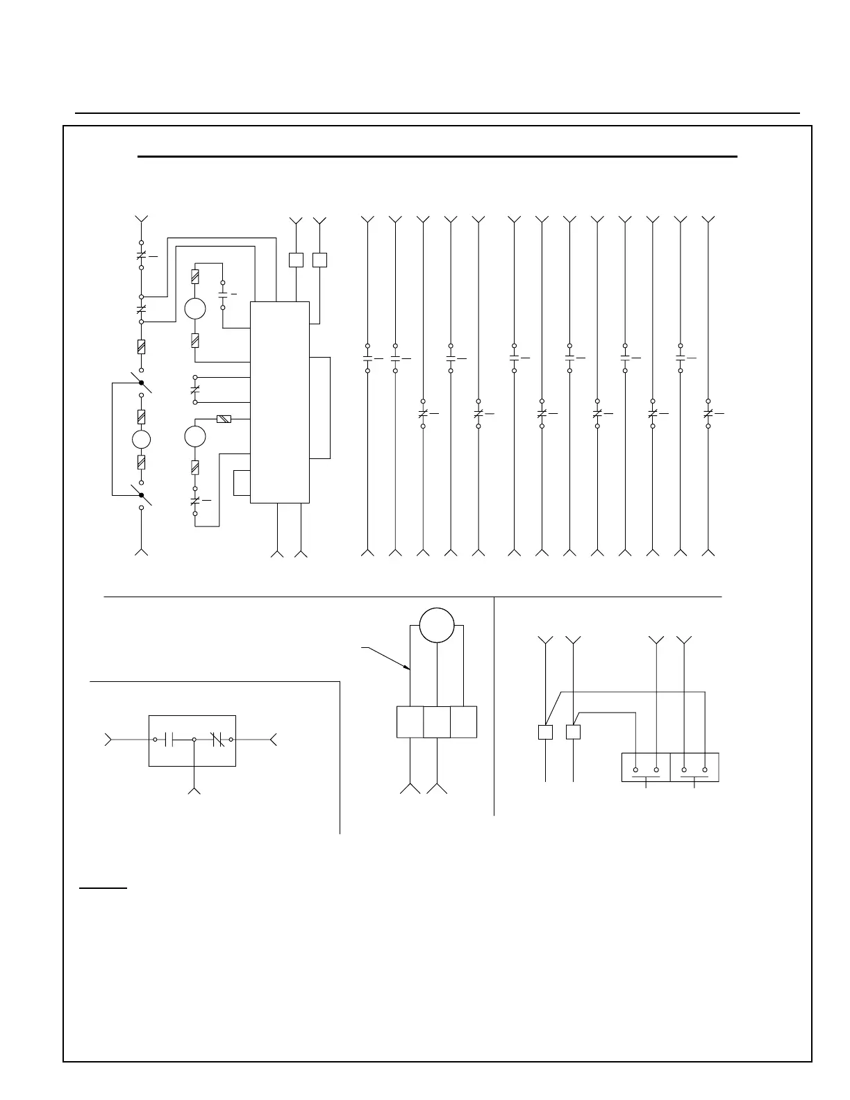
IB 6.2.11.1-1C
Page 11
ABB
NOTES:
1. This wiring diagram includes some optional features
not found on all K-Line Plus breakers, including an
alarm switch, undervoltage trip device, LET/LEC,
and spare auxiliary switch contacts.
2. Secondary disconnect numbers begin with a letter
which indicates in which plug the disconnect
resides. The “A” plug is the right-hand plug when
viewed from the rear of the breaker.
3. The spare auxiliary switch contacts which are routed
through secondary disconnect “A” are standard on
EO breakers. Those routed through plug “B” are
optional.
K-Line Plus Typical Composite Schematic (Electrically Operated)
60
58
52
59
Close+
55
54
62
Close-
MOTOR DISCONNECT SWITCH
Motor-
A7
M
CC
8
COIL
61
CLOSE
7
COIL
TRIP
b
AS
Motor+
A1
b
AS
4
3
TC
1
51
2
a
AS
Trip-
Control Device
5
P18
A5
P4
P20
P8
2
P6
A2
P2
P19
P22
P1
P10
Solid State
3A
1
3
A3
P17
4
Trip+
A4
2
P5
4A
1
7
P9
P3
80
191715
A14 A18A16
2321
A22A20
14 1816 20 22
A15 A21A19A17 A23
5
6
AS
a
10
AS
9
a
12
AS
11
b
14
AS
13
a
16
AS
15
b
53
65
CSCS
CSCS
64
63
56
57
NO
C
C
NO
B21
32
31
B22
B13B9 B11B7
3432 36
B15 B17 B19
38 40 42 44
19
17
18
a
AS
20
21
23
b
AS
22
AS
a
24
3533 37
28
27
25
AS
b
26
a
AS
29
30
AS
b
AS
a
39 41 43 45
B14B10B8 B12 B18B16 B20
46
b
AS
47
Standard Alarm Switch (Optional)
15
B1 B2
the UVD model and voltage.
breaker is dependent on
UVD wiring internal to the
26
13
27
14
UV
Undervoltage Trip Device (Optional)
Local Electrical Trip & Close (Optional)
Spare Auxiliary Switch Contacts (see notes)
A12
A10
r
A11
11
s
10
12 4B
4A3A
1 2
4
A4
3
A3
TRIP
CLOSE
3B
9
A9
8
A8
Note: The "normal" positions shown in this
figure are the switch contact postions when the
Auto Trip Indicator is "in" (reset).
P16 P13
66
 Loading...