3
KM26 | MAGNETIC LEVEL GAUGE | OI/KM26-EN REV I
This manual is designed to provide information on installing,
operating and troubleshooting or maintenance of the KM26
family of magnetic level gauge (MLG). The KM26 series
consist of the KM26S (side mounted), KM26T (top mounted),
LMG100 (Econolev), MW (MagWave) and EC (external
chamber) models.
Every section of this manual is dedicated to the specific
phases of the MLG lifecycle. The start of the lifecycle begins
with the receipt of the MLG and its identification and
continues through installation, the connection of all electrical
components, the configuration of the device (transmitters
and switches) and accessories and finally ends with the
trouble-shooting and maintenance operations.
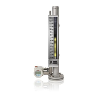
General description of KM26 MLG
The ABB model KM26S and KM26T liquid level magnetic level
gauge are designed for use in applications where a simple
gauge glass cannot or should not be used. Due to its superior
design, the KM26S and KM26T can safely be used with
flammable, corrosive or toxic liquids; or where operating
conditions exceed safety limits of glass. The rugged
construction of the KM26S and KM26T make them ideally
suited for use in operating environments where extreme
temperature and / or pressure may be encountered.
The basic KM26S and KM26T systems consist of a 1. sealed
float, 2. float chamber and 3. an indicator assembly. The float
chamber is connected directly to the process vessel.
The float contains a magnet assembly and is designed and
weighted to float in the process liquid submerged
approximately 70 to 80%. The indicator assembly consists of
a hermetically sealed glass or polycarbonate tube containing
the shuttle or magnetic bar graph indicator and a graduated
scale corresponding to the desired operating range. The
indicator assembly is mounted in close proximity to the float
chamber. Magnetic coupling exists between the float and the
indicator. As the float follows the changing liquid level, the
indicator changes position to reflect that level based on the
magnetic coupling action.
Detailed description
The float chamber of the standard KM26 is mounted as a
communicating chamber to the process vessel. It is usually
flange mounted, but different mounting options are available
upon request. Within the float chamber is a float which is
designed to float with approximately 70 to 80% of its mass
submerged in the process fluid. The float magnet assembly is
located such that the magnetic actuation point of the magnet
assembly is at the liquid level when the fluid is at the specific
gravity specified. The position of the float will vary directly
with the level of the process fluid.
The indicator assembly, consisting of a glass or polycarbonate
tube, an indicator (shuttle or magnetic bar graph) and a
graduated scale, is installed parallel and in close proximity to
the float chamber. This is necessary to allow for maximum
magnetic coupling between the float and the indicator. The
indicator and tube are mounted in a stainless steel channel
which has a graduated scale attached. The graduations on
this scale correspond to the desired operating range. The
glass indicator tube is an IP68 certified hermetically sealed
which prevent the ingress and accumulation of dust and
moisture. The indicators are painted with high visibility paint
so readings can be obtained from long distances.
Around the middle of the shuttle is a black reference line that
directly corresponds to a value on the graduated scale to
obtain the process liquid level. The shuttle tube must be in
the proper orientation for it to operate correctly and this is
determined by the rubber bumper in the glass tube. The
optional magnetic bar graph indicator is available in yellow /
black or red / white for use in locations where temperature is
not excessive. The flippers on the bar graph rotate to change
color at the fluid level. Consult the factory for applicable
temperature limits and insulated options.
The indicator tube is positioned such that the normal
downward travel of the float is stopped at a position that
corresponds to the scale zero by a spring mounted on the
bottom flange for the KM26S and a float stop tube for the
KM26T. Therefore, as long as the float and the shuttle are
magnetically coupled, the shuttle will be visible. Both the
KM26S and the KM26T are equipped with a float stop spring
at the top of the chamber. These springs absorb the force on
the float that occurs if fluid levels change rapidly in the
chamber and propel the float up or down.
1 Introduction
Figure 1 - KM26 overview
1. Float 2. Fluid contained in this chamber 3. Process connections 4.
Liquid level 5. Center of magnet assembly 6. Indicator 7. Hermetically
sealed glass tube 8. Calibrated scale
 Loading...