9
KM26 | MAGNETIC LEVEL GAUGE | OI/KM26-EN REV I
Hazardous area considerations
If the ATEX certification plate for the MLG is permanently
fixed and if any transmitters or switches and the accessories
have their own certifications. For specific conditions for safe
use of the KM26, refer to section ‘explosives atomspheres
installation’ and details for the transmitters and switches
refer to their respective manuals.
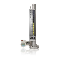
Understanding the MLG parts
The standard KM26 MLG system consists of 1. chamber 2.
float and 3. indicator assembly.
Chamber
The chamber (refer to figure 6) of the standard KM26 is
mounted as a communicating chamber to the process vessel.
It is usually flange mounted, but different mounting options
are available upon request. The typical chamber size is 2 ½ in.
S10 or S40 welded pipe depending upon the application
pressure, temperature and corrosion allowance. The standard
chamber material is 316/L however is usually the same
material as that of the process vessel or the tank. The selction
of the material is mainly depneding on the aplication
parameters and the measured media properties.The end user
shall have the responsibility to select the approriate material
of the application based on the the process parameters /
specifications. For the available material options, please refer
to the datasheet of KM26). The chamber is also engineered
with the required type and number of process connections
designed to meet the relevant ANSI and ASME codes and
welding meeting the similar requirements wherever
applicable.
Figure 6 - KM26 MLG chamber
... 2 Safety
Note
Unpack the instrument carefully. Inspect all units for damage.
Report any concealed damage to carrier within 24 hours. Do
not discard the shipping container until all parts/components
are verified and checked.
3 Mounting
General
Read the following installation instructions carefully before
proceeding. Failure to observe the warnings and instructions
may cause a malfunction or personal hazard. Before installing
the KM26, ensure the device design meets the requirements
of the measurement point from both a measure technology
and safety point of view. This applies but is not limited to the
following:
• explosion-protection certification
• measuring range
• pressure, temperature or operating voltage
Check the suitability of the materials in regards to their
resistance to the media. This applies but is not limited to the
following:
• gasket, process connection and seals
• float
• end connection, transmitter, switches and other
accessories.
In addition, the relevant directives, regulations, standards and
accident prevention regulations must be observed.
Measurement accuracy is largely dependent on the correct
installation of the KM26 MLG and, if applicable, mounting
arrangement. In instances where it is possible, the measuring
setup should be free from critical ambient conditions such as
large variations in temperature, vibrations or shocks.
All installations
• prior to installation, verify the model of the MLG is
suitable for the intended application. Information
regarding the model specifications may be found on the
corresponding KM26 series datasheets.
• if any transmitters or switches are mounted on the MLG,
ensure that the electronics housing should be maintained
as per the specified ambient conditions per the
respective datasheet of the device.
• do not use the MLG as a support when mounting.
If unfavorable ambient conditions cannot be avoided for
reasons relating to building structure, measurement
technology and / or other issues, the measurement
quality may be affected.
NOTICE