11
ABB
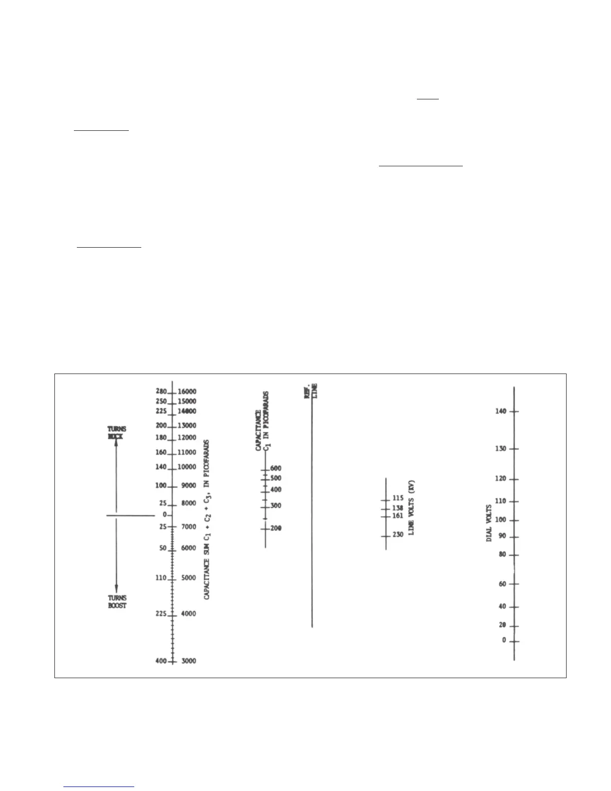
Figure 7: Nomograph for PBA2 Potential Device
Capacitance C2 similarly measured will contain an
insignificant percentage of stray capacitance.
Capacitance C1 is then:
C1=
C2 x 0.85C4
C2 – 0.85C4 (1)
Approximate adjustments may be calculated using the
nomograph (Fig. 7) and the instructions on the following
pages or the equations below.
First calculate the bushing tap voltages as if no potential
device burden were present. This is determined from the
relation:
e = E
C1
C1 + C2 + C3 (2)
Where e is the open circuit tap voltage in volts and E is the
actual system line-to-ground voltage at the condenser bushing.
The dial setting of the voltage adjustment should then total,
dial volts = 173 — e
44.1 (3)
For the phase angle adjustment it is necessary to know the
capacitive reactance XC which must be series tuned. This
value in ohms is, for 60 hertz:
XC = 10
12
377* (C1+C2+C3) (4)
*377 = 2 πf, with f = 60 hertz
Using this value of XC refer to curve Fig. 5 and using the
same value of reactance determine whether the device
reactance switch is to be in the BUCK or BOOST position
and further determine the number of turns required in the
phase angle adjustment. Now set the rotary switches and
toggle switch of the phase angle adjustment so that the
total turns are the same as that determined from the curve.