7
ABB
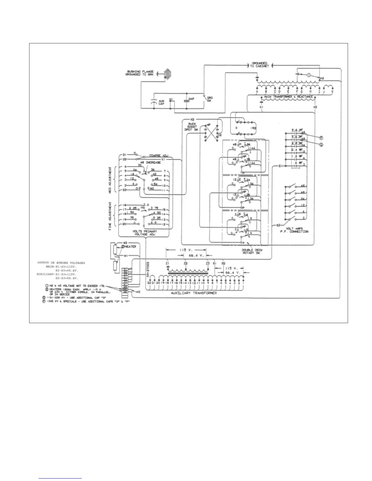
Figure 3: Connection Diagram
For this adjustment the device must be connected to its
final condenser bushing, with normal line-to-ground voltage
on the bushing stud, and with a reference voltage available
for comparison. See also ADJUSTING-GENERAL above.
The ratio or output voltage adjustment is a matter of voltage
magnitude only, and this is checked by voltmeter reading.
The phase angle of the output voltage may be checked by
low reading voltmeter, by phase angle meter or by oscillo
scope,
as previously mentioned.
Fig. 4 is the circuit diagram for checking the phase angle
and ratio using the oscilloscope with vertical and horizontal
sweeps each energized at 115 volts 60 hertz. The oscillo
scope
shall be adjusted so that the total deflection in each the
vertical and the horizontal directions is roughly the same.
The reference and the output voltages are in phase when
the trace on the oscilloscope is the nearest possible to a
single straight line. Some variation in the wave form of the
two voltages may prevent the trace from ever becoming a
perfect straight line. When the voltages are out of phase,
the trace tends to be an ellipse; it would be a circle with the
two voltages 90 degrees out of phase. The oscilloscope as
used here will not distinguish in-phase from 180
o
out-of-phase.