Feeder Terminal REF 541, REF 543, REF 545.
1MRS750443-MBG
17
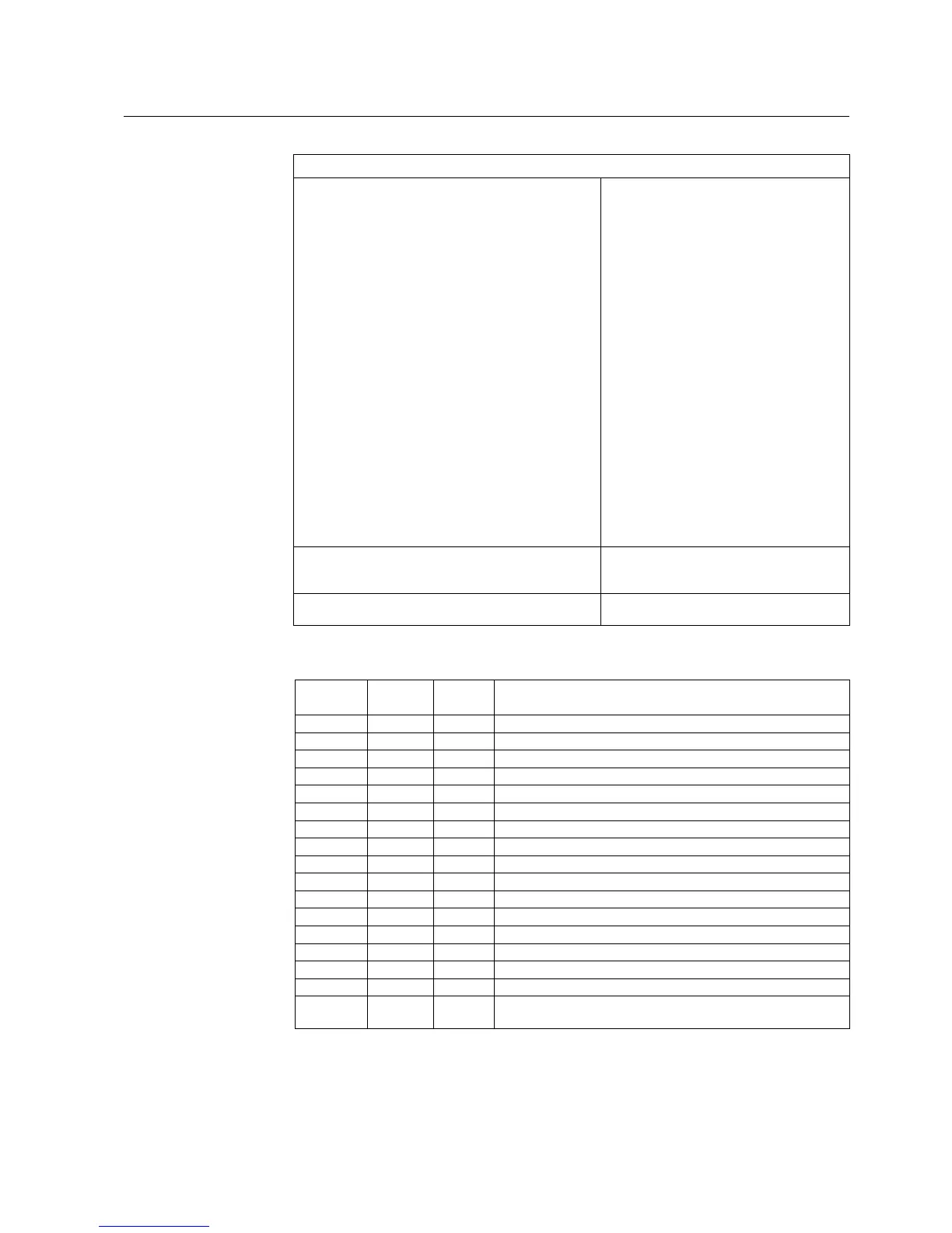
Power factor controller settings
Power factor controller, COPFC
The number of capacitor banks to be controlled
The relational step sizes and the type of the switching
sequence
Size of the first capacitor bank (should be the smallest)
Target value for daytime cos
Day unit
Target value for night-time cos
Night unit
Setting the reconnection inhibit time (discharge time)
Sensitivity in the inductive side
Sensitivity in the capacitive side
Alarm limit for the maximum reactive power
Alarm limit for the minimum reactive power
Overvoltage limit when the switching in is inhibited
Operation mode
Starting the automatic testing sequence
Calculation method
Control principle
Duration demand
Day&night switch
Manual command
1...4
1:1:1:1 linear; 1:1:1:1 circul.; 1:1:2:2 circul.;
1:2:2:2 linear; 1:2:2:2 circul.; 1:2:4:4 linear;
1:2:4:4 circul.; 1:2:4:8
10.0...50000.0 kvar
0.70...1.00
Inductive; Capacitive
0.70...1.00
Inductive; Capacitive
0.5...6000.0 s
60.0...200.0%
0.0...100.0%
0.1...100.0 Mvar
-100.0...0.0 Mvar
0.80...1.60 x Un
Not in use; Automatic mode; Manual mode;
Testing mode
Not activated; Start
Normal; Integral
Progressive; Direct
0.5...6000.0 s
Not in use; Digital input; Internal clock;
By setting
Not activated; Remove one step; Add one
step; Disconnect all
Recorded data
Number of switching operations per day
Number of switching operations per week
0...65535
0...65535
Operation accuracies
Accuracy class of operation
2.0% of set value or 0.02 x rated value
2.0
Table 5: Measurement functions
Function ANSI
device no.
IEC
symbol
Description
MEAI1
2)
AI1 AI1 General measurement 1 / analog input on RTD/analog module
MEAI2
2)
AI2 AI2 General measurement 2 / analog input on RTD/analog module
MEAI3
2)
AI3 AI3 General measurement 3 / analog input on RTD/analog module
MEAI4
2)
AI4 AI4 General measurement 4 / analog input on RTD/analog module
MEAI5
2)
AI5 AI5 General measurement 5 / analog input on RTD/analog module
MEAI6
2)
AI6 AI6 General measurement 6 / analog input on RTD/analog module
MEAI7
2)
AI7 AI7 General measurement 7 / analog input on RTD/analog module
MEAI8
2)
AI8 AI8 General measurement 8 / analog input on RTD/analog module
MEAO1
2)
AO1 AO1 Analog output 1 on RTD/analog module
MEAO2
2)
AO1 AO1 Analog output 2 on RTD/analog module
MEAO3
2)
AO3 AO3 Analog output 3 on RTD/analog module
MEAO4
2)
AO4 AO4 Analog output 4 on RTD/analog module
MECU1A Io Io Neutral current measurement, stage A
MECU1B Io_B Io_B Neutral current measurement, stage B
MECU3A 3I 3I Three-phase current measurement, stage A
MECU3B
2)
3I_B 3I_B Three-phase current measurement, stage B
MEDREC16
1)
DREC DREC Transient disturbance recorder