Feeder Terminal REF 541, REF 543, REF 545.
1MRS750443-MBG
52
Hardware versions of REF 541,
REF 543 and REF 545
For the number of digital inputs and outputs
of REF 54_ feeder terminals, refer to the
tables above. The number of matching trans
-
formers, sensor inputs and analogue inputs
and outputs, and the auxiliary voltage range
vary between the different hardware versions
of REF54_. Each hardware version of REF
541 and REF 543 can be supplied with an
RTD/analogue module.
Software configuration
Each REF 54_ feeder terminal allows various
software configurations based on separate
functions. Functions included in the selected
functionality level can be activated within the
scope of the I/O connections and considering
the total CPU load of the functions.
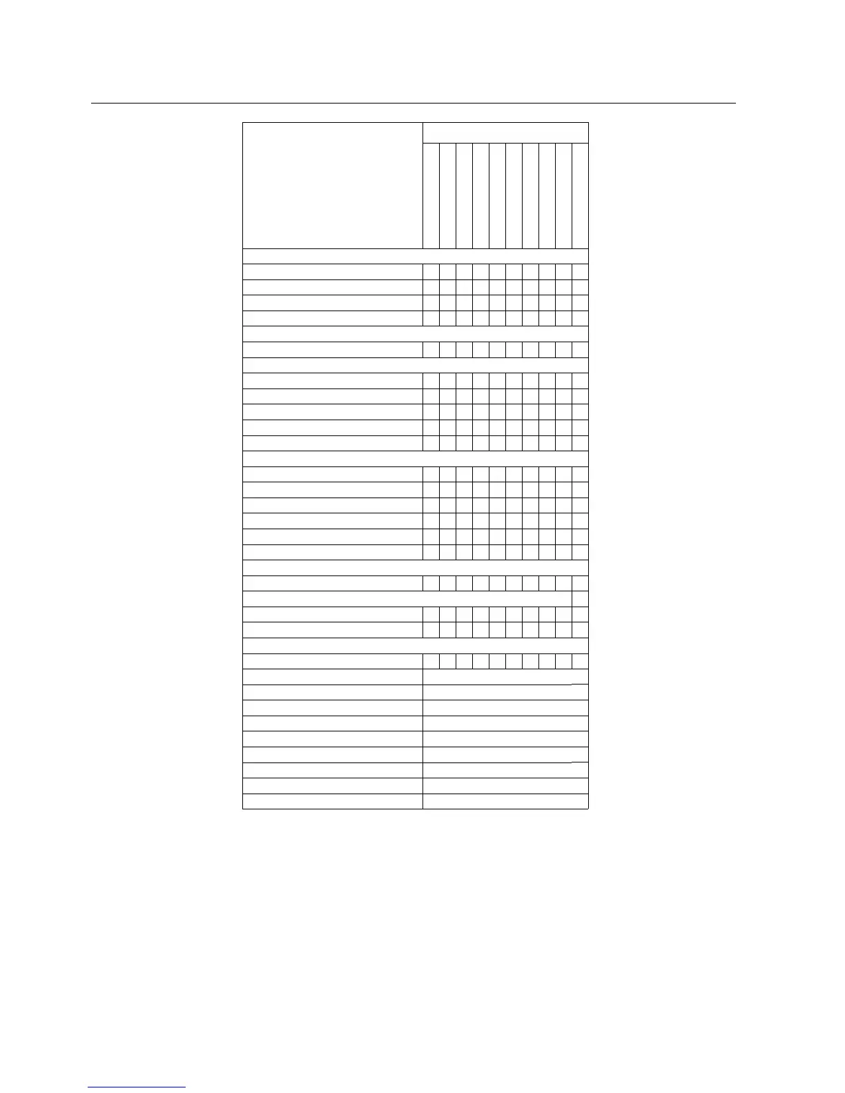
Hardware modules of REF 545 Order number
REF545K_133AAAA
REF545K_133BAAA
REF545K_133CAAA
REF545K_133AABA
REF545K_133BABA
REF545K_133CABA
REF545K_133AAAB
REF545K_133BAAB
REF545K_133AABB
REF545K_133BABB
Analogue interface
Sensor channels (current or voltage) 9 9 9 9 9
Current transformer 1/5 A 4 4 4 4 4 4 4 4 4 4
Current transformer 0.2/1 A 1 1 1 1 1 1 1 1 1 1
Voltage transformer 100 V 4 4 4 4 4 4 4 4 4 4
Main processor boards
CPU module 1 1 1 1 1 1 1 1 1 1
Power supply boards
PS1: 80...265 Vdc/ac (High)
PS1: 80...265 Vdc/ac (Medium)
PS1: 18...80 Vdc (Low)
PS2: 80...265 Vdc/ac 1 1 1 1 1 1 1 1
PS2: 18...80 Vdc 1 1
Digital I/O boards
BIO1: threshold voltage 155 Vdc 2 2 2 2
BIO1: threshold voltage 80 Vdc 2 2 2 2
BIO1: threshold voltage 18 Vdc 2 2
BIO2: threshold voltage 155 Vdc 1 1 1 1
BIO2: threshold voltage 80 Vdc 1 1 1 1
BIO2: threshold voltage 18 Vdc 1 1
Analogue I/O board
RTD/analogue module
Display boards
Graphic HMI display, fixed 1 1 1 1 1 1
Graphic HMI display, external 1 1 1 1
Mechanical design
1/2 enclosure 1 1 1 1 1 1 1 1 1 1
Digital inputs 34
Power outputs, single-pole 3
Power outputs, double-pole 11
Signal outputs (NO) 4
Signal outputs (NO/NC) 8
Supervised trip circuits 2
IRF outputs 1
RTD/analogue inputs 0
Analogue outputs 0