13
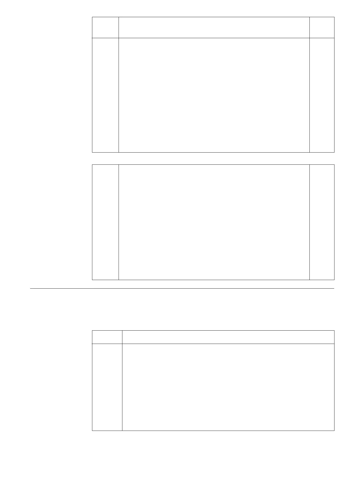
Output relay matrix
switchgroups SGR1
and SGR2
Switch Function Factory
setting
SGR1/1 When SGR1/1=1, the overload stage I
a
> alarm output is linked to SS1 0
SGR1/2 When SGR1/2=1, the overload stage I
b
> start signal is linked to SS1 0
SGR1/3 When SGR1/3=1, the unbalance stage ∆I
1
> alarm signal is linked to SS1 0
SGR1/4 When SGR1/4=1, the unbalance stage ∆I
2
> start signal is linked to SS1 1
SGR1/5 When SGR1/5=1, the overload stage I
a
> alarm output is linked to SS3 1
SGR1/6 When SGR1/6=1, the overload stage I
b
> trip signal is linked to SS3 0
SGR1/7 When SGR1/7=1, the unbalance stage ∆I
2
> trip signal is linked to SS3 0
SGR1/8 When SGR1/8=1, the undercurrent I< trip signal is linked to SS3 0
SGR2/1 When SGR2/1=1, the overload stage I
a
> alarm output is linked to SS2 0
SGR2/2 When SGR2/2=1, the overload stage I
b
> start signal is linked to SS2 1
SGR2/3 When SGR2/3=1, the overload stage I
b
> trip signal is linked to SS2 0
SGR2/4 When SGR2/4=1, the unbalance stage ∆I
1
> alarm signal is linked to SS2 0
SGR2/5 When SGR2/5=1, the unbalance stage ∆I
2
> start signal is linked to SS2 0
SGR2/6 When SGR2/6=1, the unbalance stage ∆I
2
> trip signal is linked to SS2 0
SGR2/7 When SGR2/7=1, the undercurrent I< trip signal is linked to SS2 0
SGR2/8 When SGR2/8=1, the external trip is linked to SS3 0
Measured data
The measured values are shown by the three
right-most digits of the display. The currently
measured data are indicated by an illuminated
LED indicator on the front panel.
Note!
A symbol "//" in the text indicates that the fol-
lowing item is found in a submenu.
Indicator Measured data
I
L1
Filtered current on phase L1 as a multiple of the rated current I
n
I
L2
Filtered current on phase L2 as a multiple of the rated current I
n
I
L3
Filtered current on phase L3 as a multiple of the rated current I
n
Note!
The filtered phase currents are proportional to the phase voltages over
the capacitor bank.
∆I
c
Compensated unbalance current ∆I
c
as a percentage of unbalance input rated
current ∆I
n
. // Unbalance current ∆I as a percentage of unbalance input rated
current ∆I
n
.