6
The capacitor bank relay contains one external
logic control input, which is activated by a con-
trol signal of the auxiliary voltage level. The in-
fluence of the control input on the relay is de-
termined by programming switches of the meas-
uring module. The control input can be used
either for blocking one or more of the protec-
tive stages, for carrying out an external trip or-
der, for inhibiting a reconnection attempt or/
and for resetting a latched output relay in the
manual reset mode.
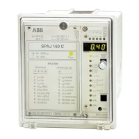
The protective relay is provided with a man-
machine interface on the front panel. The man-
machine interface shows relay activation's, meas-
ured values, maximum value registrations, start-
ing counters, time counters and setting values.
All changes of setting values can be made by
using the push-buttons on the front panel.
Through the serial bus the man-machine com-
munication can be obtained either by using a
PC with a setting tool program, a SCS local
control system or a microSCADA remote con-
trol system.
Fig. 7. Checking functions of the capacitor bank overload and unbalance prot. relay type
SPAJ 160 C.
SIGNAL 1
IL1
IL2
IL3
I
SIGNAL 2
COMPENSATION FOR NATURAL
PHASE UNBALANCE
37
∆∆
∆∆
62
51N
OVERLOAD PROTECTION
CAPACITOR BANK PROTECTION
WITH ALARM/TRIP STAGE
UNDERCURRENT DETECTION
FOR RECONNECTION INHIBIT
RECONNECTION INHIBIT TIMER
SERIAL COMMUNICATION
TRIP
START
RECONNECTION
ENABLE
IRF
SERIAL I/O
CONTROL
INPUT BS1

 Loading...