10
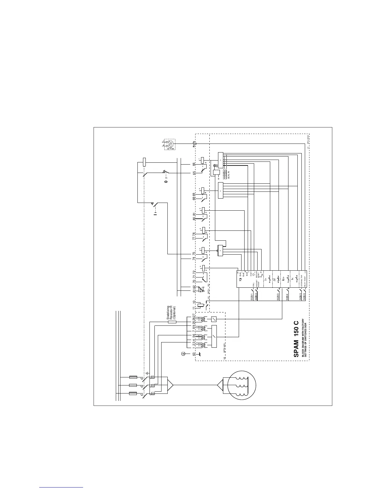
Should a unit other than the overload protec-
tion or start-up stress monitor of the relay trip,
the condition of the motor should be checked.
For that reason the operation of the output re-
lay A (contacts 65 - 66) is selected to be manu-
ally reset after a trip by means of switch SGB/7.
If the latching function is wanted for all trip
operations, switch SGB/8 is used instead of the
former switch.
Simultaneously with the trip relay, a signalling
relay B is operated, giving a trip signal over con-
tacts 68 - 69.
A prior alarm for a beginning overheating is
achieved with relay D (contacts 77 - 78) as soon
as the thermal level exceeds the set prior alarm
level θ
a
. This level can preferably be set at e.g.
90%, allowing the motor to be fully utilized at
nominal current, but giving an alarm as soon as
the load is constantly higher than the full load
current.
A too rapid restart attempt is prevented by the
restart inhibit feature in the relay.The close sig-
nal to the contactor or circuit breaker is linked
over the restart enable relay E contact (74 - 75).
The relay will not allow a restart until the ther-
mal level of the motor is lower than the set re-
start inhibit level θ
i
.
Figure 6. A contactor controlled motor drive with residually connected earth-fault protection. To
stabilize against virtual earth-faults an external resistor is added in the return path for the earth-
fault current to increase the burden for the main CTs.
Note! A power and output relay module type SPGU 240 R3 or SPGU 48 R3 is used for a nor-
mally closed trip contact for contactor controlled drive use.
L1
L2
L3
I
0
Uaux
Stabilizing
Resistor R
(Optional)
See Note!
Internal
Relay
Fault
Motor
Restart
Enable
Startup
Information
from Motor
Thermal
Prior
Alarm
Signal for
Tripped
Motor
Trip
Output
Relay
+
-
External
Control
Input
63
6261
1 A
5 A
1 A
5 A
1 A
5 A
252627123456789
1 A
5 A
70 71 72
Rx Tx
65
66
IRF
68 6977 7874 75
80 81
10
11
1 1
SGB/1
SGB/2
U1/SGB/7
U1/SGB/8
SGB/3
TRIP
R
SEAL-IN
Σ >
ts
1
+
B
+
C
+
F
+
E
+
D
+
A
3
SGB/4
STALL
I/O
I»
Io>
I<
START
∆I
I t
2
RESTART
INHIBIT
RESTART
INHIBIT
SGB/5
RELAY RESET
θ>θ
i
θ>θ
a
θ>θ
t
SGB/6
EXTERNAL TRIP
U1 SPCJ 4D34
U3 SPTK 4E3
U2 SPTU _ R2
s
s
BLOCK DIAGRAM WITH FACTORY
SETTINGS OF SWITCHES SGR
SPAM 150 C

 Loading...


