12 ABB Power Distribution
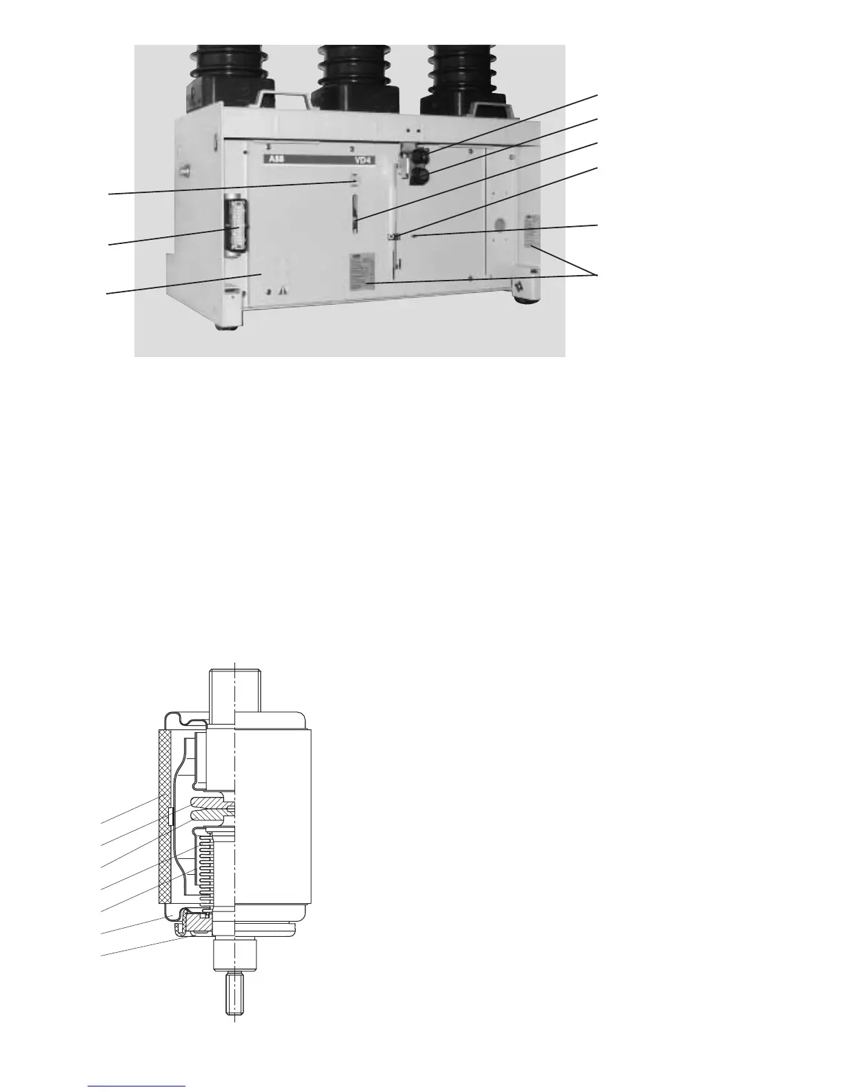
50.7
56.1
55.8
55.7
55.4
55.5
55.6
54.3
54.2
Figure 3/4: Controls for the circuit-breaker
50.7 Front plate
54.2 Mechanical ON push-button
54.3 Mechanical OFF push-button
55.4 Switch position indicator
55.5 Operating cycle counter
55.6 Socket (for charging level)
55.7 Rating plate
55.8 Charging condition indicator
56.1 Control wiring socket, 24-pole version
(64-pole version on request)
Figure 3/5: Partial section of a vacuum interrupter 58, simplified
schematic diagram
Details vary according to the specified switching duties.
58.1 Insulator
58.2 Fixed contact
58.3 Movable contact
58.4 Metal bellows
58.5 Screen
58.6 Guide
58.7 Interrupter lid
58.1
58.2
58.3
58.4
58.5
58.7
58.6

 Loading...


