18 VD4X INSTRUCTION MANUAL
—
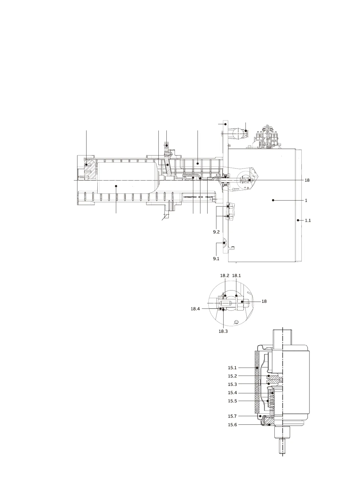
Figure 3/2: Sectional
view of a vacuum
circuit-breaker, type
VD4X-U.
—
Figure 3/3: Partial
section of vacuum
interrupter, simplified
schematic diagram
(details are
dependent on the
stipulated ratings)
1)
1)
13
1214 11
9
33
15 16 17 19
—
Figure 3/2
—
Figure 3/3
1) Busbar connection arranged above or below the breaker pole
depending on the switchgear system.
1 Circuit-breaker operating mechanism
1.1 Front plate
9 Mounting plate
9.1 O-ring
9.2 Operating mechanism mounting
11 Insulating material pole half shell
12 Breaker terminal
13 Front breaker terminal
14 Flexible conductor
15 Vacuum interrupter
16 Contact force spring
17 Insulating push-rod
18 Lock nut
18.1 Spring washer
18.2 Retaining plate
18.3 Positioning plate
18.4 Washer
19 Gas-tight thrust bushing
33 Pressure sensor for circuit-breaker compartment
15.1 Insulator
15.2 Fixed contact
15.3 Moving contact
15.4 Metal bellows
15.5 Screen
15.6 Guide
15.7 Interrupter lid