STRUCTURE AND MODE OF ACTION 19
—
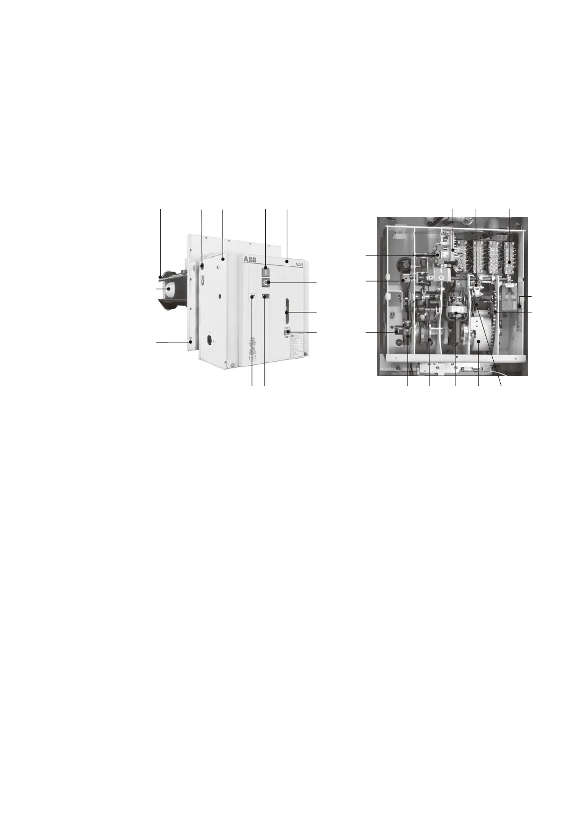
Figure 3/4: Vacuum
circuit-breaker type
VD4X
—
Figure 3/5:
Stored-energy
spring mechanism
with auxiliary
equipment –
front plate removed.
Design variant
where conventional
secondary
equipment is used
—
Figure 3/4
—
Figure 3/5
25
26
34 6
27
28 24 23
22
21 20
11
10
1.2 1 2 1.1
9
5 4
6
8
3
35
7
1 Circuit-breaker operating mechanism
1.1 Front plate
1.2 Bore for handling, both sides
2 Mechanical ON push-button
3 Mechanical OFF push-button
4 Mechanical position indicator
5 Mechanical operating cycle counter
6 Recess for charging lever (emergency manual operation)
8 Mechanical charging condition indicator
9 Mounting plate
10 Breaker pole
11 Insulating material pole tube
6 Recess for charging lever 32
7 Rating plate
20 Ratchet wheel
21 Charging motor
22 Chain drive
23 Drum with spiral spring
24 Release and control mechanism on the mechanism shaft
25 Opening spring
26 Release and control mechanism area
27 Mechanism shaft
28 Cam disc
34 Magnet holder, complete
35 Auxiliary switch block (e.g. with -BGS1,-BGB2,-BGB1 and -BGB3)