Page 11
EXERCISE 12 : FLOATING PINS / DRIVEN PINS
ACTION
Press START on IC Tester. Observe 'FLOT IPML' on pin 10.
Press INPUT DRIVEN switch to apply drive to Pin 10 from output on pin 11.
Observe FLOT signal change to L1 and also an L1 appearing on pin 11.
DESCRIPTION
In this step the circuit shows that there is a connection to input pin 10 but it is not being
driven as the relay is not being energised. Although there is no drive to the input it is not
registering as an open circuit due to the level of impedance measured.
Operating the 'INPUT DRIVEN' switch connects the output from Pin 11 to the input of Pin 10
via the relay. This shows how pins that are directly linked together are identified. The FLOT
indication is removed as the pin now has a valid logic level driven to it.
COMMENT
Floating pins are a common occurrence on TTL type devices. Whenever there is a Floating pin
identified there is likely be an indication of a MID LEVEL voltage. As the pin is not being
driven by a valid logic level and is floating between, there will be an indication of a Mid-High
or a Mid -Low voltage.
It is most important that you understand that this condition will be normal if the device has
a floating pin due to its lack of connection to another device. For instance, if the input comes
from a connector normally used in the system there may be an open circuit or a floating pin
displayed depending on the device it normally drives. It is not immediately recognised as a
fault condition, in most cases it would be a circuit condition.
Referencing against a good board or the schematics or even following the track to its source
can quickly verify the situation.
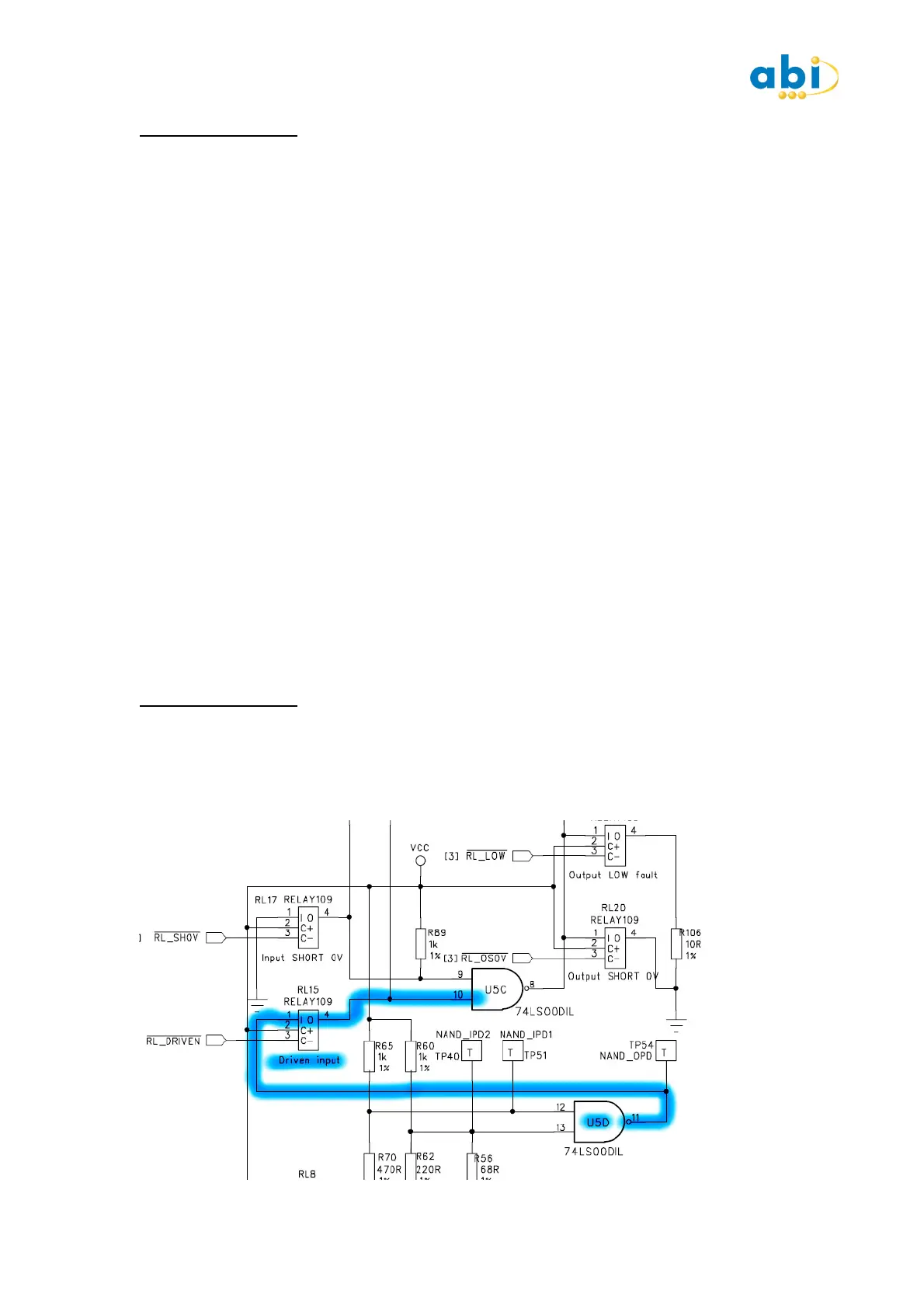
EXERCISE 13 : LINKED PINS
ACTION
Press START on the IC Tester.
Press the INPUT DRIVEN switch and verify Pins 10 & 11 each show L1.
Press the VALID LINK switch. Pins 1 & 2 now show L1 and pins 10 & 11 show L2.
 Loading...