Page 12
DESCRIPTION
The Connections test finds Links by changing the input state of one pin and monitoring all
subsequent pins for the same change. Pins found to be linked in this manner are then
checked by reversing the order of test. There is no limit to how many pins can be shown as
linked but there is differentiation between the groups as can be seen by two pins with L1
(one linked pair) and L2 (a separate linked pair not linked to L1).
COMMENTS
There is no significance in the numbering of pairs or groups of pins. The order is governed
by the Links seen first by the Connections test. A sign of activity on a PCB may be that the
links are constantly changing and moving about.
This would indicate a fast moving signal but it would also depend on the device operation for
instance a flip-flip with a high speed clock could give some confusing results with mid-levels
and linked pins if you were not aware of how the test results are obtained.
EXERCISE 14 : MID LEVEL INPUTS
ACTION
Press START on the IC Tester.
Press INPUT MID HIGH switch and observe the input on Pin 12 change to IPMH.
Press INPUT MID LOW switch and observe the input on Pin 13 change to IPML
DESCRIPTION
Supplying the input through a potential divider creates both of the conditions. Note from the
circuit that external components as well as fault conditions can create Mid-Levels.
COMMENT
Input Mid-Low and Input Mid-High can be present for a large number of reasons not
necessarily due to a fault condition. Circuit design and circuit conditions generally do present
mid-levels.
A fast changing signal will show a mid-level result, some open collector configurations will
show mid-levels due to pull-up resistor values. Each occurrence of mid-level input should be
considered along with what you know of the circuit and what other IC's in the circuit
show.Mid Level inputs generally do not give reason for a Truth Table test to fail. As long as
the tester can backdrive the signal the response from the IC should remain good. If the Mid-
level cannot be driven to a valid logic level then it will be identified as a problem.
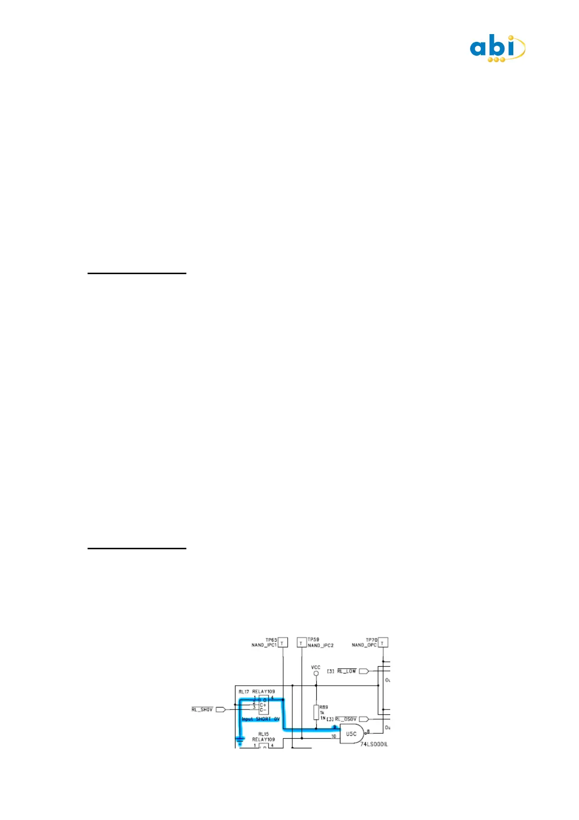
EXERCISE 15 : INPUT SHORTS
ACTION
Press START on the IC Tester. Observe Truth Table test is PASS. Press SHORT 5V switch.
Observe change to Pin 4 and note the Truth Table test continues to PASS. Press SHORT 0V
button. Observe change to Pin 9 and note the Truth Table test continues to PASS.
Note the change to Pin 10 from FLOT to OPCT.
 Loading...