Page 13
DESCRIPTION
The shorted pins are directly connected to VCC & GND. The tester cannot drive these pins
and they remain in the same state throughout the test. Stimulus is not applied to the pins
and the Truth Table test is adjusted accordingly.
The OPCT indication on Pin 9 would, in normal circumstances indicate a pin not being driven
and not presenting any impedance.For CMOS it could be normal condition from high
impedance inputs, it could be a broken bond wire in IC, Tri-state output in OFF state or even
a bad clip connection.
In this case it represents the normal behaviour of a TTL gate with multiple inputs. When one
input is Floating and the other input is pulled LOW or to GND the internal diode structure of
the gate presents a high impedance to the tester on the floating pin. This is a typical feature
on TTL devices.
COMMENT
The Shorts presented to the inputs are taken into account as valid circuit conditions when the
Truth Table test is run. This test shows the ability of the system to adapt to different circuit
conditions and still give valid results for the IC Test without any operator intervention. In this
instance the end result tells you that the device is operating correctly for how it is wired,
whether the circuit conditions seen are valid would need the Connections tests to be run in
comparison with the results of a good board or checked against the schematic
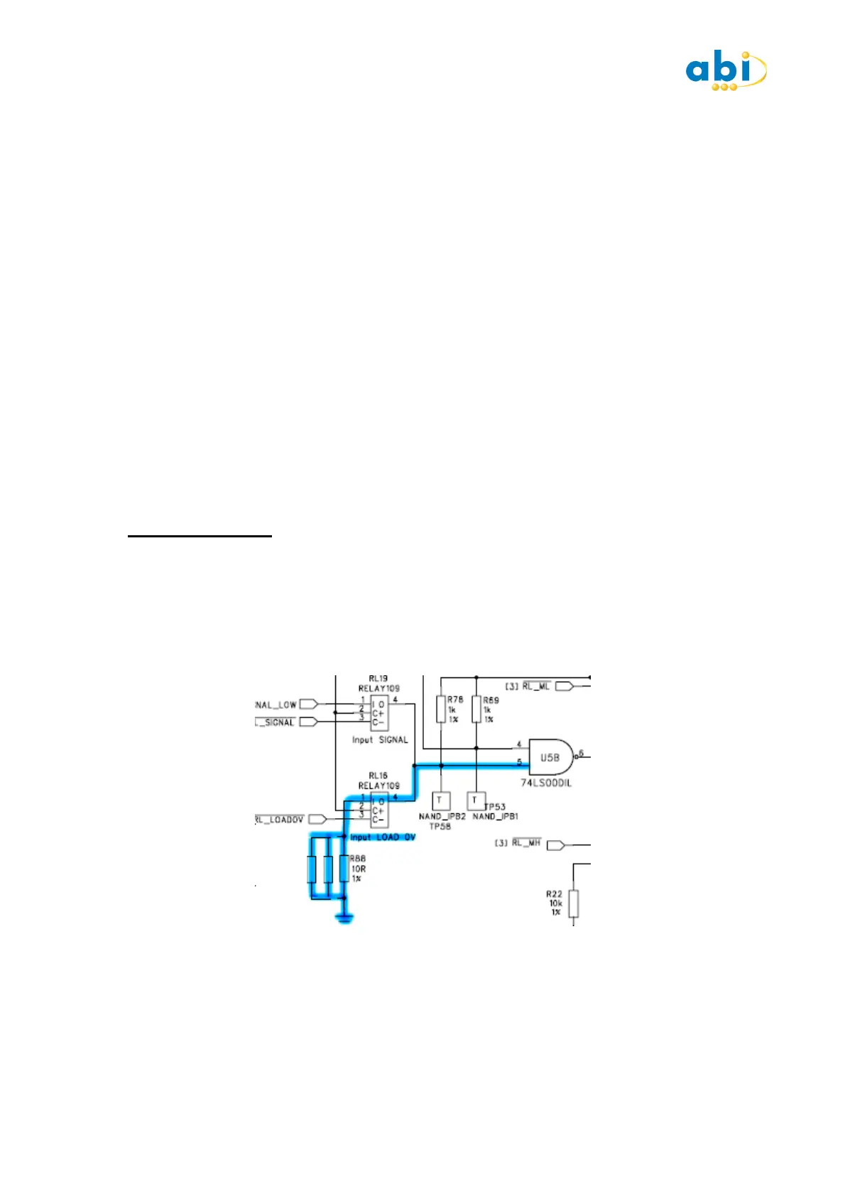
EXERCISE 16 : INPUT LOADS
ACTION
Press START on the IC Tester.
Press INPUT LOAD 0V switch and observe change to Pin 5.
Press INPUT LOAD 5V switch and observe Pin 13
Note the Truth Table continues to show PASS.
 Loading...