Page 6
COMMENTS
If you require a higher current for the UUT you can use an external supply for testing. It is
important that the external supply isreferenced to the BFL ground so that its measurements
are accurate. By not doing this it might be that the BFL will detect High Voltages and not start
the test.
EXERCISE 4 : VOLTAGE TEST
ACTION
Connect 64-way split cable to the Board Fault Locator Module (If using a BoardMaster the
bottom module is the Primary test module).
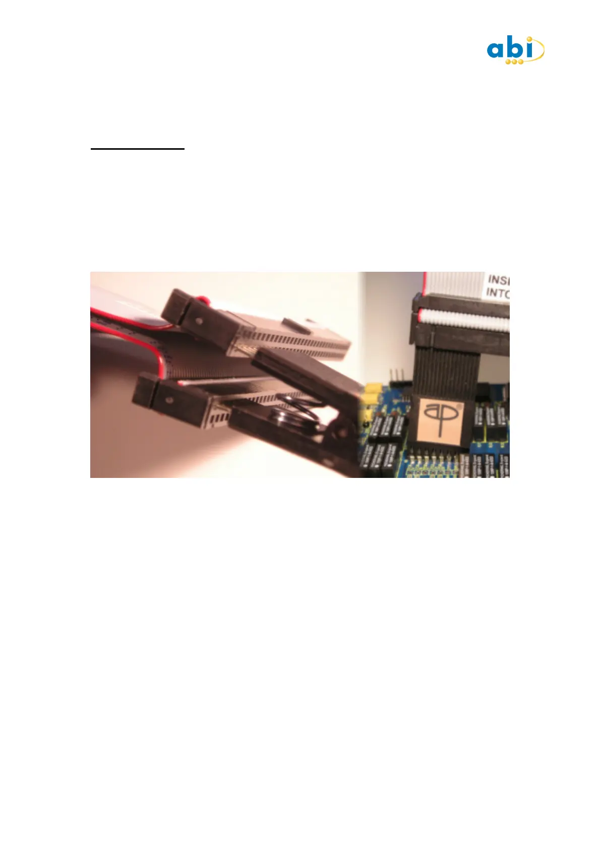
Attach a 14,16 or 20 way DIL test clip to the black connectors on the 64 way cable with the
red stripe. Ensuring the clip is placed on the inner rows and towards the red stripe. (Cable is
labelled accordingly.) Attach clip to IC U5 with red stripe orientated toward the pin 1 end of
IC (see below) :
Press the SETUP button and take note of the Type and Mode settings as well as the
Thresholds. Close the SETUP window.
Press the START button and observe the IC diagram dragging the test results display to one
side if necessary.
DESCRIPTION
The Voltage test quite simply looks at the voltage on each pin in turn and displays the result.
Much like measuring each IC pin with a Multimeter but much quicker. When the voltage test
is selected on its own the clip is not automatically orientated due to the passive nature of the
test.
Clipping Pin 1 of the tester to Pin 1 of the IC makes it easy to identify which reading
corresponds to IC pin. When used independently each pin has an indication of the logic level
the voltage corresponds to. The logic level thresholds can be seen in the SETUP window and
the default settings are those for the device you have selected to test.
COMMENTS
It is advisable to run the voltage test in a Loop mode so that you can see if the DUT is active.
Changing logic states could indicate active signals on the PCB and device which may have to
be given special consideration when reviewing the later tests.
 Loading...