Do you have a question about the Abloy DA461 and is the answer not in the manual?
Provides specifications like dimensions, weight, voltage, and enclosure class.
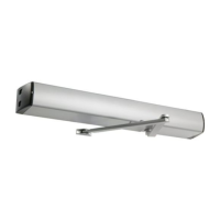
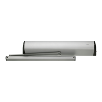
Lists key functionalities and characteristics of the door operator.
Details the function and operation of the main and mode switches on the unit.
Lists the necessary tools for installation.
Outlines the sequence of actions for installing the door operator.
Describes pre-installation checks and door preparation steps.
Instructions on how to safely remove the operator's housing.
Guides on mounting the DA104 plate to the transom.
Details attaching the operator and arms to the closing side of the door.
Guides on mounting the operator and sliding arm to the closing side.
Instructions for attaching the operator and sliding arm to the opening side.
Explains how to remove the position sensor for adjustments.
Covers the adjustment of door closing speeds.
Details how to adjust the closing force of the door closer.
Initial check for smooth door operation before commissioning.
Setting the mode switch to manual operation.
Selecting the correct arm type for the installation.
Configuring settings based on door size and type.
Verifying optional configurations like fire detector input.
Setting up and enabling safety sensor monitoring.
Programming the open and closed positions of the door.
Adjusting the door's opening speed and hold-open duration.
Details on activating and using the Push & Go feature.
Final checks to ensure the operator functions correctly.
Guidelines for setting speed and force for safe door operation.
Recommendation for fitting safety sensors for enhanced safety.
Pinout and function of the X2 connector.
How to connect the fire detector system to the operator.
Instructions for wiring the safety sensor to the unit.
Wiring example for safety sensors.
Connection diagram for DA061 microwave motion sensor.
Wiring example for DA063 microwave motion sensor.
Connection diagram for the DA033 elbow switch.
Wiring example for DA039 and DA049 rotary switches.
Connection diagram for various electric locks.
Wiring example for EL490 and EL590 motor locks.
Diagram and operation for a fire door system integration.
Explains fault codes and control unit LED indicators for diagnostics.
Provides corrective actions for control unit malfunctions.
Indicates normal states and alert conditions for safetysensors.
Describes monitoring errors and how to check safetysensor connections.
Outlines recommended service intervals for door operators.
Lists key inspection points during maintenance service.
Lists part numbers for various components like head panel, motor, and arms.
| Brand | Abloy |
|---|---|
| Model | DA461 |
| Category | Garage Door Opener |
| Power Consumption | 4.8W |
| Operating Temperature | -20°C to +60°C |
| Protection Class | IP54 |
| Material | Stainless steel |